Specifications Information and Replacement Parts Manual | ||
|
Please read and save this Repair Parts Manual. Read this manual and the General Operating Instructions carefully before attempting to assemble, operate or maintain the product described. Protect yourself and others by observing all safety information. The Safety Instructions are contained in the General Operating Instructions. Failure to comply with the safety instructions accompanying this product could result in personal injury and/or property damage! Retain instructions for future reference.
Vertical Sealless Sprayer/Washer Pumps
Refer to form
Description
Vertical sealless sprayer/washer pumps are heavy duty industrial units designed for OEM, automotive and industrial washing machines, parts cleaners, spray booths and cooling towers. Pumps are immersion type; pump end must be immersed in liquid, motor must remain above liquid surface.
All models feature 316 stainless steel
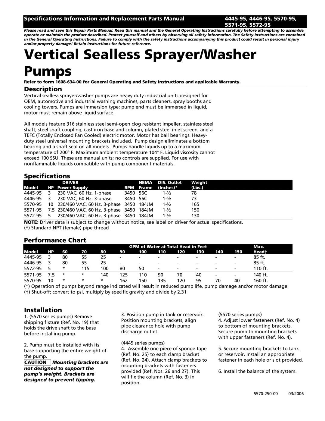
Specifications
|
| DRIVER |
| NEMA | DIS. Outlet | Weight |
Model | HP | Power Supply | RPM | Frame | (Inches)* | (Lbs.) |
3 | 230 VAC, 60 Hz. | 3450 | 56C | 78 | ||
3 | 230 VAC, 60 Hz. | 3450 | 56C | 73 | ||
10 | 230/460 VAC, 60 Hz. | 3450 | 184JM | 165 | ||
7.5 | 230/460 VAC, 60 Hz. | 3450 | 184JM | 150 | ||
5 | 230/460 VAC, 60 Hz. | 3450 | 184JM | 130 |
NOTE: Driver data is subject to change without notice, see label on driver for actual specifications.
(*) Standard NPT (female) pipe thread
Performance Chart
|
|
|
|
|
| GPM of Water at Total Head in Feet |
|
| Max. | |||
Model | HP | 60 | 70 | 80 | 90 | 100 | 110 | 120 | 130 | 140 | 150 | Head† |
3 | 80 | 55 | 25 | - | - | - | - | - | - | - | 85 ft. | |
3 | 80 | 55 | 25 | - | - | - | - | - | - | - | 85 ft. | |
5 | * | 115 | 100 | 80 | 50 | - | - | - | - | - | 110 ft. | |
|
|
|
|
|
|
|
|
|
|
|
|
|
7.5 | * | * | 140 | 125 | 110 | 90 | 70 | 40 | - | - | 140 ft. | |
10 | * | * | * | 162 | 150 | 135 | 120 | 95 | 70 | 40 | 160 ft. | |
(*)Operation of pumps beyond range indicated will result in reduced pump life, pump damage and/or motor damage. (†)
Installation
1.(5570 series pumps) Remove shipping fixture (Ref. No. 19) that holds the drive shaft to the base before installing pump.
2.Pump must be installed with its base supporting the entire weight of the pump.
CAUTION Mounting brackets are not designed to support the pump’s weight. Brackets are designed to prevent tipping.
3.Position pump in tank or reservoir. Position mounting brackets, align pipe clearance hole with pump discharge outlet.
(4445 series pumps)
4.Assemble one piece of sponge tape (Ref. No. 25) to each clamp bracket (Ref. No. 24). Attach clamp brackets to mounting brackets with fasteners provided (Ref. Nos. 26 and 27). This will fix the column (Ref. No. 3) in position.
(5570 series pumps)
4.Adjust lower fasteners (Ref. No. 4) to bottom of mounting brackets. Secure pump to mounting brackets with upper fasteners (Ref. No. 4).
5.Secure mounting brackets to tank or reservoir. Install an appropriate fastener in each hole or slot provided.
6.Install the balance of the system.
