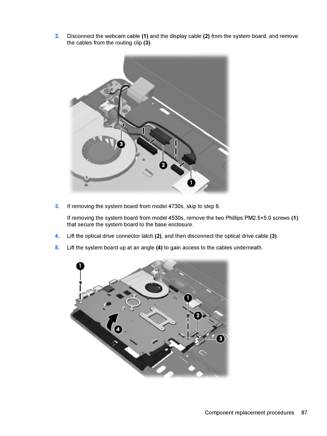
2.Disconnect the webcam cable (1) and the display cable (2) from the system board, and remove the cables from the routing clip (3).
3.If removing the system board from model 4730s, skip to step 6.
If removing the system board from model 4530s, remove the two Phillips PM2.5×5.0 screws (1) that secure the system board to the base enclosure.
4.Lift the optical drive connector latch (2), and then disconnect the optical drive cable (3).
5.Lift the system board up at an angle (4) to gain access to the cables underneath.
