20
7.25 TREADMILL
 ASSEMBLY
STEP 2:
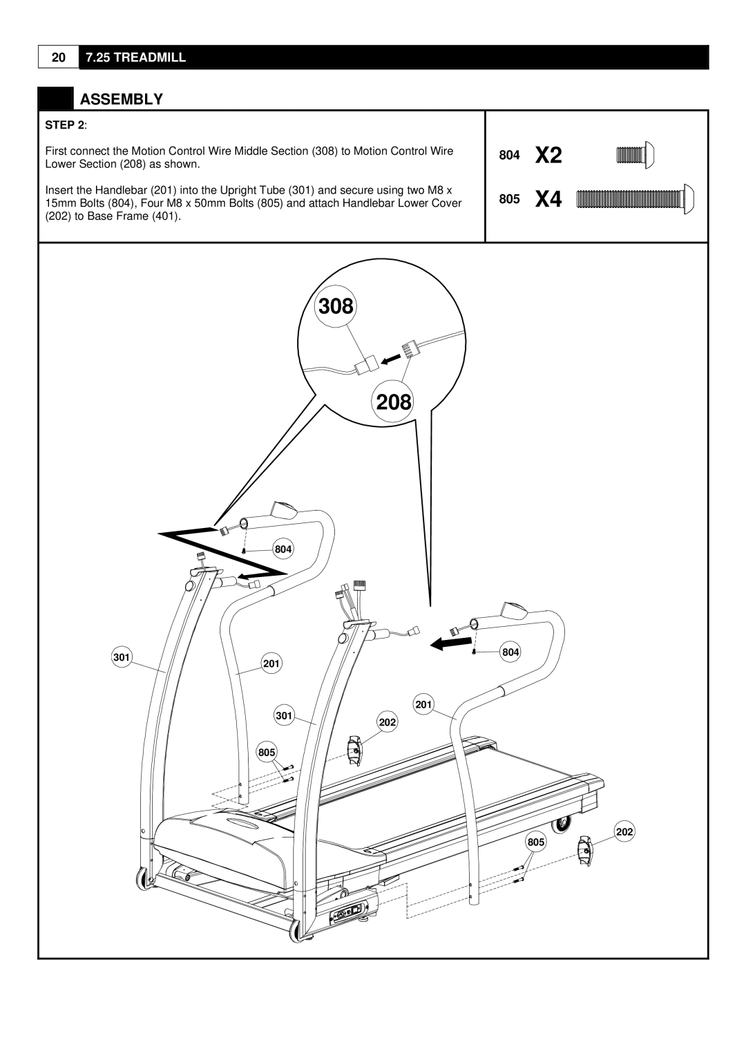
First connect the Motion Control Wire Middle Section (308) to Motion Control Wire Lower Section (208) as shown.
Insert the Handlebar (201) into the Upright Tube (301) and secure using two M8 x 15mm Bolts (804), Four M8 x 50mm Bolts (805) and attach Handlebar Lower Cover (202) to Base Frame (401).
804X2
805X4
308
208
804
301 | 804 | |
201 | ||
|
201
301202
805
202
805
