22
7.25 TREADMILL

 ASSEMBLY
STEP 4:
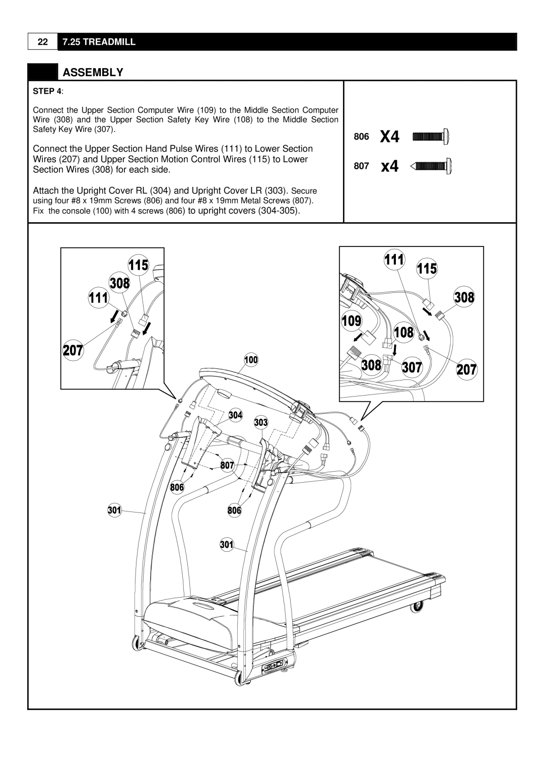
Connect the Upper Section Computer Wire (109) to the Middle Section Computer Wire (308) and the Upper Section Safety Key Wire (108) to the Middle Section Safety Key Wire (307).
Connect the Upper Section Hand Pulse Wires (111) to Lower Section Wires (207) and Upper Section Motion Control Wires (115) to Lower Section Wires (308) for each side.
Attach the Upright Cover RL (304) and Upright Cover LR (303). Secure using four #8 x 19mm Screws (806) and four #8 x 19mm Metal Screws (807). Fix the console (100) with 4 screws (806) to upright covers