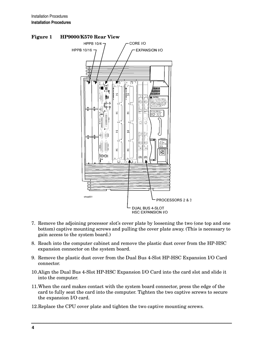
K570, A3694A specifications
The HP A3694A is a well-regarded device in the realm of printers and copiers, notably designed for high-performance printing in various professional settings. The HP K570, on the other hand, is known as a multi-functional printer that emphasizes efficiency and reliability. Both models exemplify HP's commitment to innovation and quality.The A3694A features advanced laser printing technology that delivers crisp, sharp text and vivid images at impressive speeds. With a print resolution of up to 1200x1200 dpi, it ensures that documents are not only produced quickly but also with exceptional clarity. The device is optimized for heavy-duty workloads, making it an excellent choice for busy offices that require consistent performance and high-volume printing capabilities.
One of the hallmark characteristics of the A3694A is its ability to handle various media types and sizes. This flexibility allows users to print everything from standard letter-sized documents to larger presentations and marketing materials without compromising on quality. It also includes a variety of connectivity options, including USB and network interfaces, which facilitate seamless integration into existing office setups.
Furthermore, the HP K570 incorporates several cutting-edge technologies that enhance its functionality. This multi-functional printer boasts capabilities for printing, scanning, copying, and faxing, making it an all-in-one solution for diverse office tasks. The K570 is designed with user-friendly features, including a straightforward control panel and an intuitive user interface that minimizes the learning curve for staff members.
The printing mechanism of the K570 utilizes thermal inkjet technology, which not only ensures high-quality output but also supports a diverse array of ink types, suitable for various projects. The device is capable of achieving print speeds that meet the demands of fast-paced work environments, while its energy-efficient design helps in reducing operational costs.
Moreover, both the A3694A and K570 include functionalities that support mobile printing, allowing users to send documents from their smartphones or tablets directly to the printer. The incorporation of wireless connectivity features, such as Wi-Fi Direct and Apple AirPrint, aligns with the growing trend toward mobile and remote printing solutions.
In summary, the HP A3694A and K570 are exemplary devices that showcase HP's dedication to delivering high-performance, versatile, and user-friendly printing solutions. With their advanced technologies and robust features, they are suitable for any modern office environment looking to enhance productivity and efficiency.

