GlassWare Audio Design | 3 |
Remember, tubes are not yardsticks that never change, being more like car tires— they wear out. Just as a tire’s weight and diameter decrease over time, so too the tube’s conductance. So the fresh 6DJ8 is not the same as that same 6DJ8 after 2,000 hours of use. But as long as the two triodes age in the same way— which they are inclined to do, as they do the same amount of work and share the same materials and environment— the Aikido amplifier will always bias up correctly, splitting the B+ voltage between the triodes. Moreover, the Aikido amplifier does not make huge popping swings at start up, as the output does not start at the B+ and then swing down a hundred or so volts when the tube heats up, as it does in a
This circuit eliminates power- supply noise from the output, by injecting the same amount of PS noise at the top and bottom of the
If the output connection is taken from the output cathode follower's cathode, then the balance will be broken. The same holds true if the cathode follower's cathode resistor is removed. (Besides, this resistor actually makes for a better sounding cathode follower, as it linearizes the cathode follower at the expense of a higher output impedance. Unfortunately, it should be removed and the bypass capacitor C3 should be used when driving
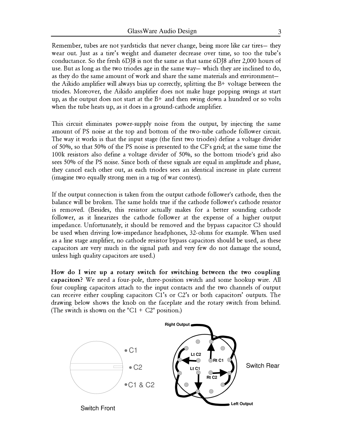
How do I wire up a rotary switch for switching between the two coupling capacitors? We need a four- pole,
| Right Output |
C1 | Lt C2 |
| |
| Rt C1 |
C2 | Lt C1 |
Rt C2
 C1 & C2
Switch Rear
Left Output
Switch Front