Configuring the PCB as a Headphone Amplifier
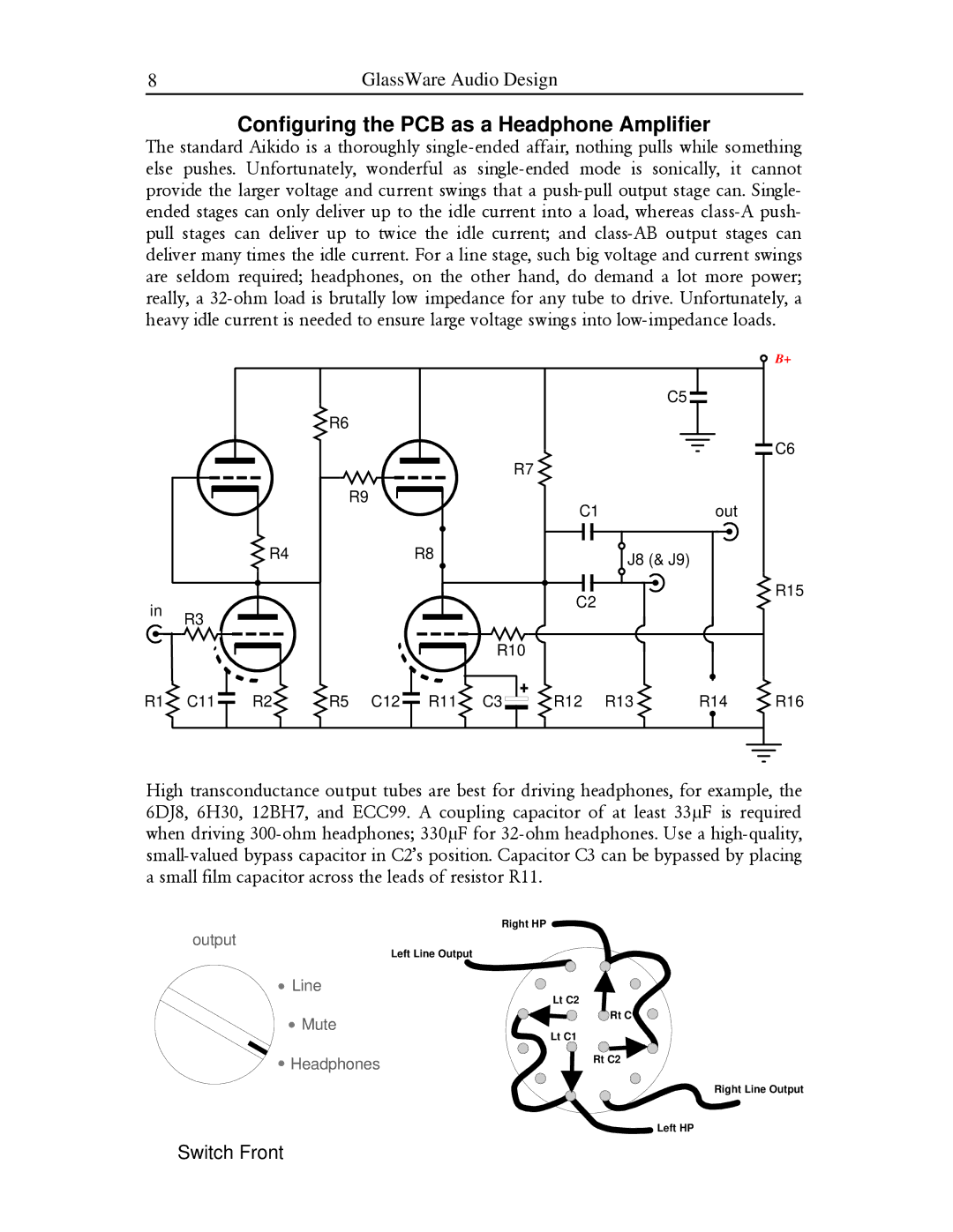
The standard Aikido is a thoroughly single-ended affair, nothing pulls while something else pushes. Unfortunately, wonderful as single-ended mode is sonically, it cannot provide the larger voltage and current swings that a push-pull output stage can. Single- ended stages can only deliver up to the idle current into a load, whereas class-A push- pull stages can deliver up to twice the idle current; and class-AB output stages can deliver many times the idle current. For a line stage, such big voltage and current swings are seldom required; headphones, on the other hand, do demand a lot more power; really, a 32-ohm load is brutally low impedance for any tube to drive. Unfortunately, a heavy idle current is needed to ensure large voltage swings into low-impedance loads.
| | | | | | | | | | B+ |
| | | | | | | | C5 | | |
| | | R6 | | | | | | | |
| | | | | | | | | | C6 |
| | | | | | R7 | | | | |
| | | R9 | | | | C1 | | out | |
| | | | | | | | |
| | R4 | | | R8 | | | J8 (& J9) | | |
| | | | | | | | | |
| | | | | | | C2 | | | R15 |
in | R3 | | | | | | | | |
| | | | | | | | |
| | | | | | | | | |
| | | | | | R10 | | | | |
R1 | C11 | R2 | R5 | C12 | R11 | C3 | R12 | R13 | R14 | R16 |
High transconductance output tubes are best for driving headphones, for example, the 6DJ8, 6H30, 12BH7, and ECC99. A coupling capacitor of at least 33µF is required when driving 300-ohm headphones; 330µF for 32-ohm headphones. Use a high-quality, small-valued bypass capacitor in C2’s position. Capacitor C3 can be bypassed by placing a small film capacitor across the leads of resistor R11.
Right HP
output
Left Line Output
Line
 Mute
Mute
 Headphones
Lt C2
 Rt C1
Rt C1
Lt C1
Rt C2
Right Line Output
Switch Front

![]() Mute
Mute![]() Headphones
Headphones![]() Rt C1
Rt C1