Rear Panel Components
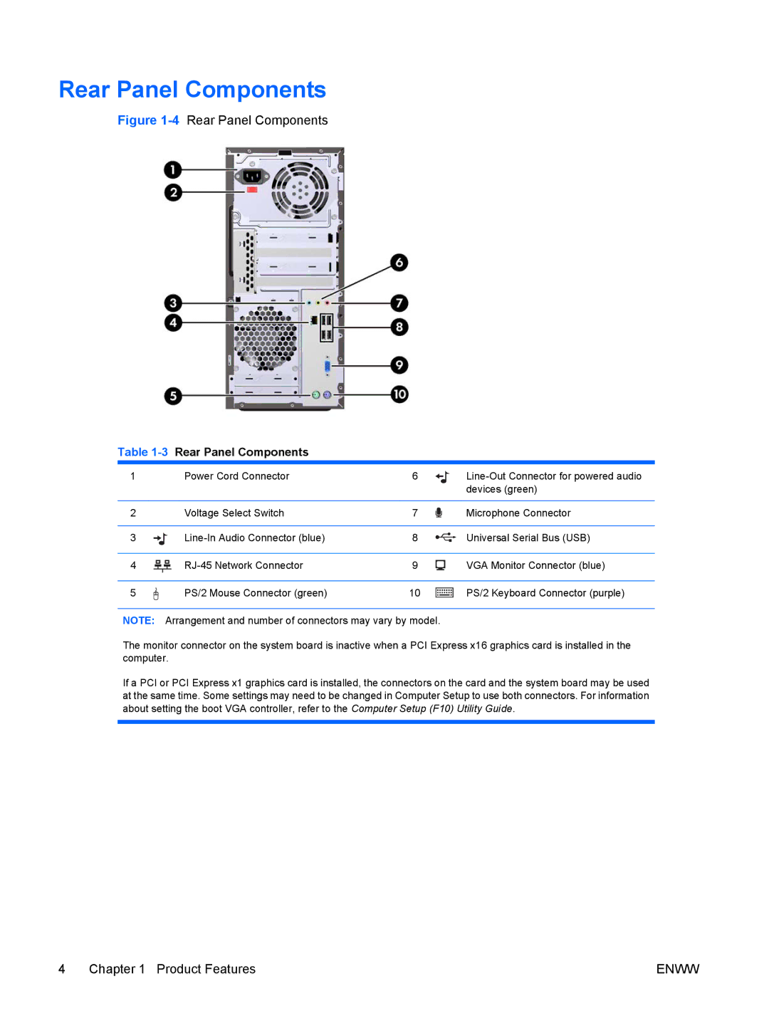
Figure 1-4 Rear Panel Components
Table 1-3 Rear Panel Components
1 | Power Cord Connector | 6 | |
|
|
| devices (green) |
|
|
|
|
2 | Voltage Select Switch | 7 | Microphone Connector |
|
|
|
|
3 | 8 | Universal Serial Bus (USB) | |
|
|
|
|
4 | 9 | VGA Monitor Connector (blue) | |
|
|
|
|
5 | PS/2 Mouse Connector (green) | 10 | PS/2 Keyboard Connector (purple) |
NOTE: Arrangement and number of connectors may vary by model.
The monitor connector on the system board is inactive when a PCI Express x16 graphics card is installed in the computer.
If a PCI or PCI Express x1 graphics card is installed, the connectors on the card and the system board may be used at the same time. Some settings may need to be changed in Computer Setup to use both connectors. For information about setting the boot VGA controller, refer to the Computer Setup (F10) Utility Guide.
4 Chapter 1 Product Features | ENWW |