6.W3φ4W = WR(L1) + WS(L2) WT(L3)
KVA 3φ 4W = ![]() KW2 3φ 4W + KVAR 2 3φ 4W
KW2 3φ 4W + KVAR 2 3φ 4W
PF3φ 4W = KW 3φ 4W
KVA 3φ 4W
7. Set the rotary switch to another position to exit this mode and clear the stored data.
NOTE
1.The "+" sign printed on meter must face the power source for accurate measurement.
2.If the device under test is switching power supply, the KW, PF and θ readings may not be correct.
NOTE
For 3φ4W power measurements, WR or WS and WT must be positive. If one shows negative power, check the connections.
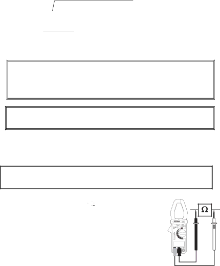
Resistance and Audible Continuity Measurements
WARNING
Before taking any
1. Set the rotary switch to the ‘Ω, ’![]()
![]()
![]()
![]() ’ or ‘MΩ’ position.
’ or ‘MΩ’ position.
2. Insert the test leads into the input jacks. (Black to ‘COM’ and Red to ‘Ω’)
3. Connect the test leads to the circuit or component under test.
4. Read the resistance value on the LCD.
5. For measurements < 40Ω, the continuity beeper will sound.
13 | 380976 | V3.1 | 6/08 |
