Shertech Operating Instructions, Performance,
Specifications and Parts Manual
Bronze Models GCBN2V, GCBN3V, GCBN22V and GCBN33V Cast Iron Models GCCV2V, GCCV3V, GCCV22V and GCCV33V
6.Be certain all suction piping connec- tions are airtight.
NOTE: Assure airtight pipe connections with the use of a pipe joint sealant.
DISCHARGE
1.Attach discharge piping to the discharge outlet.
Support pump and piping during assem-
bly and after installation. Failure to do so may cause piping to break, pump to fail, motor bearing failures, etc. All of which can result in property damage and/or personal injury.
NOTE: Should the pump need to be
2.If a
Shutting off discharge without
providing pressure relief can cause extreme
3.Operation under
NOTE: Globe valve or other restrictive valves should not be used as
4.After all piping and controls (not supplied with unit) have been installed, unit is ready for operation.
Operation
Do not run pump dry, as permanent damage
to the pump gears, seal, and bearings will result. Suction pressure should never be greater than the discharge pressure.
1.All pumps must be primed before
2.Gear pumps are built to very close tolerances and this tolerance must not be altered. The liquids must, therefore, be free of all abrasives. Sand, silt, wettable powders, etc. must be avoided.
NOTE: Cast iron pumps are for
3.When pumping a more viscous (beyond 500 SSU) liquid, a slower speed, a larger pipe size pump, and possibly a larger motor should be selected.
NOTE: See performance chart for Max. Torque.
4.Recheck motor rotation. Proper motor/pump rotation is clockwise (CW) looking at the motor shaft (See Figure 3).
5.On all models, the pressure relief valve is always on discharge side (See Figure 3).
PRESSURE RELIEF VALVE
6.Standard model rotary gear pumps are supplied with a
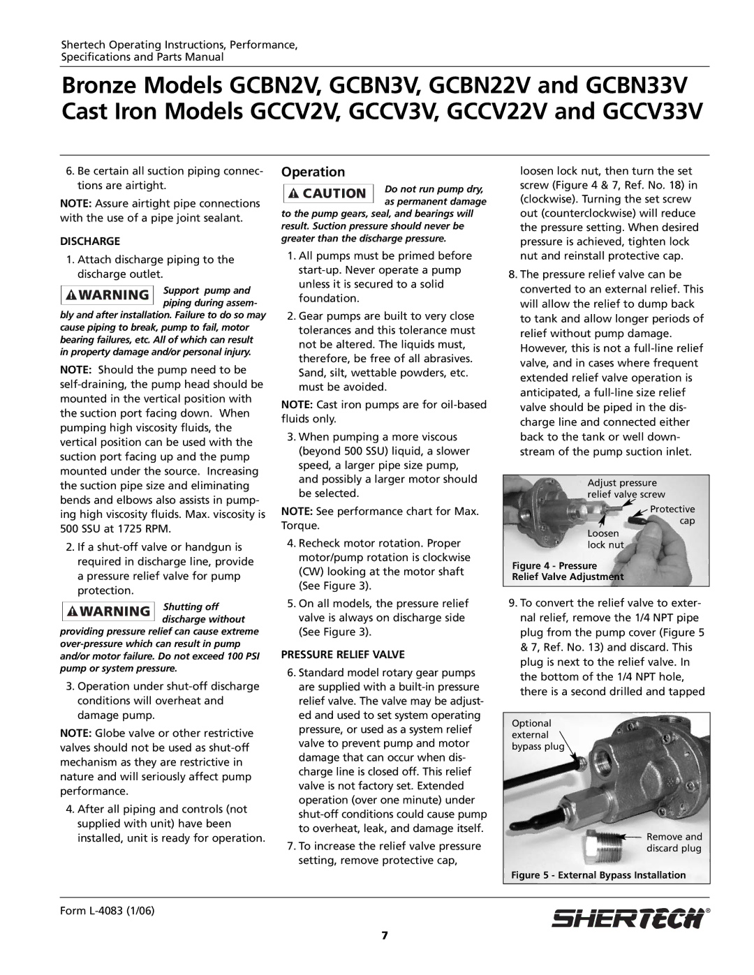
7.To increase the relief valve pressure setting, remove protective cap,
loosen lock nut, then turn the set screw (Figure 4 & 7, Ref. No. 18) in (clockwise). Turning the set screw out (counterclockwise) will reduce the pressure setting. When desired pressure is achieved, tighten lock nut and reinstall protective cap.
8.The pressure relief valve can be converted to an external relief. This will allow the relief to dump back to tank and allow longer periods of relief without pump damage. However, this is not a
Adjust pressure relief valve screw
![]() Protective
Protective
cap Loosen
lock nut
Figure 4 - Pressure
Relief Valve Adjustment
9.To convert the relief valve to exter- nal relief, remove the 1/4 NPT pipe plug from the pump cover (Figure 5 & 7, Ref. No. 13) and discard. This plug is next to the relief valve. In the bottom of the 1/4 NPT hole, there is a second drilled and tapped
Optional external bypass plug
![]() Remove and discard plug
Remove and discard plug
Figure 5 - External Bypass Installation
Form L-4083 (1/06)
7