Maintenance and Service Guide
Page
Contents
Removal and Replacement Preliminaries
Removal and Replacement Procedures
Screw Listing Index
Product Description
Key Description Options
Models
HP Compaq nc6000 Model Naming Conventions
HP Compaq nc6000 Models
DJ256A UUG
DP894A UUF
DP895A UUF
DJ324S ABD
DT868A ABA
DT412C UUF
DS798P ABG
Features
Product Description
Clearing a Password
Power Management
External Components
Front and Left-Side Components
Component Function
Rear Panel and Right-Side Components
Rear Panel and Right-Side Components
Keyboard Components
Keyboard Components
Caps lock key
Top Components
Top Components
Top Components
Top Components
Bottom Components
Bottom Components
Design Overview
Troubleshooting
Computer Setup and Diagnostics Utilities
Using Computer Setup
File Menu
Select To Do This
Selecting from the Security Menu
Security Menu
Selecting from the Advanced Menu
Advanced Menu
Advanced Menu
Using Diagnostics for Windows
Obtaining, Saving, or Printing Configuration Information
Obtaining, Saving, or Printing Diagnostic Test Information
Troubleshooting
Troubleshooting Flowcharts
Flowchart Description
Flowchart 2.1-Initial Troubleshooting
Power?
Flowchart 2.2-No Power, Part
Flowchart 2.3-No Power, Part
Flowchart 2.2-No Power, Part
Flowchart 2.4-No Power, Part
Flowchart 2.3-No Power, Part
Flowchart 2.5-No Power, Part
Flowchart 2.6-No Video, Part
Flowchart 2.7-No Video, Part
Flowchart 2.6-No Video, Part
Flowchart 2.8-Nonfunctioning Port Replicator if applicable
Nonfunctioning Port Replicator Reseat power Cord in Port
Flowchart 2.9-No Operating System OS Loading
Go to Flowchart 2.13-No OS Loading, Diskette Drive
Flowchart 2.10-No OS Loading, Hard Drive, Part
OS not Loading from Hard drive
Flowchart 2.11-No OS Loading, Hard Drive, Part
Flowchart 2.12-No OS Loading, Hard Drive, Part
Flowchart No OS Loading, Hard Drive Part
Flowchart 2.13-No OS Loading, Diskette Drive
Flowchart 2.14-No OS Loading, CD- or DVD-ROM Drive
Flowchart 2.15-No Audio, Part
Undock
Flowchart 2.16-No Audio, Part
Flowchart 2.17-Nonfunctioning Device
Cmos
Flowchart 2.18-Nonfunctioning Keyboard
Flowchart 2.19-Nonfunctioning Pointing Device
Flowchart 2.20-No Network/Modem Connection
Network
Illustrated Parts Catalog
Serial Number Location
Illustrated Parts Catalog
Spare Parts Notebook Major Components
Item Description Number
Illustrated Parts Catalog
Spare Part
Description Number
Illustrated Parts Catalog
Bluetooth wireless communications board
Item Description
Miscellaneous Plastics Kit
Miscellaneous Plastics Kit Components Spare Part Number
Mass Storage Devices
Mass Storage Devices Spare Part Number Information
Miscellaneous
Misc
Spare Part Description Number
Sequential Part Number Listing
Spare Parts Sequential Part Number Listing
Spare Parts Sequential Part Number Listing
Spare Parts Sequential Part Number Listing
Spare Parts Sequential Part Number Listing
Spare Part Number Description
Removal and Replacement Preliminaries
Tools Required
Service Considerations
Plastic Parts
Preventing Damage to Removable Drives
Packaging and Transporting Precautions
Preventing Electrostatic Damage
Workstation Precautions
Grounding Equipment and Methods
Event 10% 40% 55%
Typical Electrostatic Voltage Levels
Static-Shielding Materials
Material Use Voltage Protection Level
Removal and Replacement Procedures
Serial Number
# of Screws
Disassembly Sequence Chart
Disassembly Sequence Chart
Section Description Removed
LED board Button board System board Screws Standoffs
Preparing the Notebook for Disassembly
Removing the Battery Pack
Removing the Battery Bezel
Removing the Hard Drive Screws
Removing the Hard Drive
Removing the Hard Drive Bracket and Connector
Replacing the Notebook Feet
Wireless LAN cards
Mini PCI Communications Board
Removing the Mini PCI Compartment Cover
Removal and Replacement Procedures
Removing the Mini PCI Communications Board
MultiBay Device
Bluetooth Wireless Communications Board
Reverse the above procedure to install a Bluetooth board
Integrated Smart Card
Removing the Smart Card
Keyboard
Releasing the Keyboard
Reverse the above procedure to install the keyboard
Modem Board
Memory Expansion Board
Removing a Memory Expansion Board
Switch Cover
Reverse the above procedure to install the switch cover
Keyboard Plate
Security Module TPM
Fan Assembly
Removing the Fan Assembly
Reverse the above procedure to install the fan assembly
Heat Sink
Removing the Heat Sink
Reverse the above procedure to install the heat sink
Processor
Reverse the above procedure to install the processor
Display Assembly
Disconnecting the Display Cables
Removing the Display Screws
Reverse the above procedure to install the display assembly
Top Cover
Removing the Top Cover Screws
Reverse the above procedure to install the top cover
RTC Battery
Lift the RTC battery out of the top cover clip
LED Board
Reverse the above procedure to install the LED board
Button Board
Reverse the above procedure to install the button board
System Board
Removing the System Board Screws and Standoffs
Reverse the above procedure to install the system board
Specifications
Relative humidity noncondensing
Inch, SXGA+, TFT Display
Inch, XGA, TFT Display
Hard Drives
60-GB 40-GB 30-GB
Primary 6-Cell, Li-Ion Battery Pack
External AC Adapter
Optional High-Capacity 8-Cell, Li-Ion Battery Pack
Optional MultiBay 8-Cell, Li-Ion Battery Pack
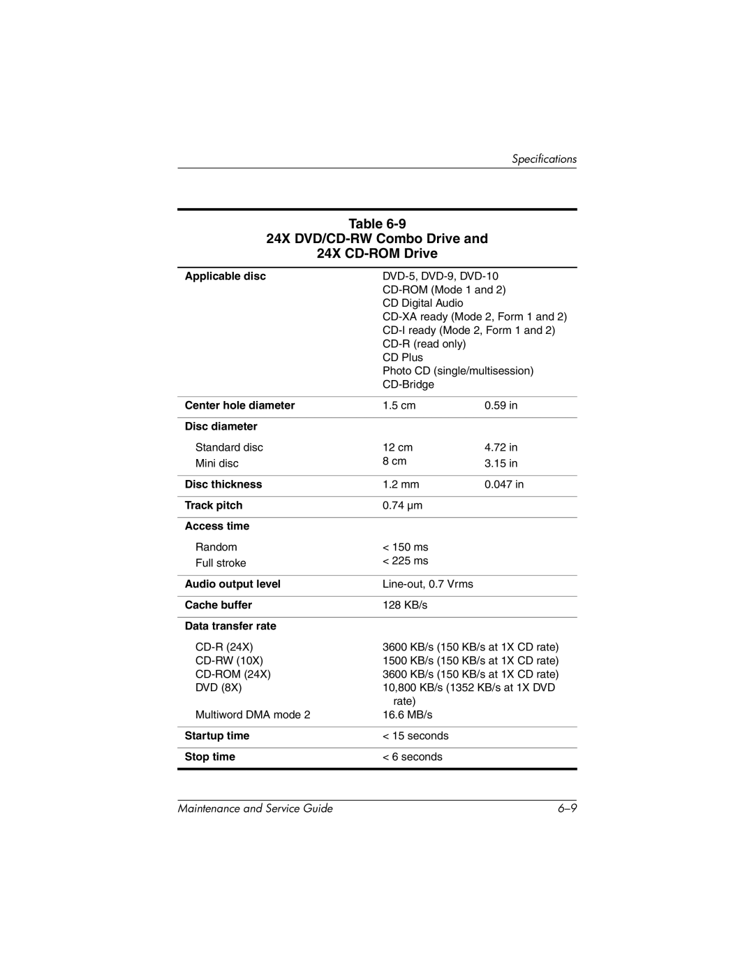
24X DVD/CD-RW Combo Drive
8X DVD-ROM Drive DVD+RW/R and CD-RW Combo Drive
System DMA
Hardware System
System Interrupts
IRQ
System I/O Addresses
Address System Function
16F Unused
VGA
Connector Pin Assignments
Table A-1 RJ-45 Network Interface
Table A-2 RJ-11 Modem
Table A-3 Universal Serial Bus
Table A-4 Video
Table A-5 External Monitor
Table A-6 Audio Line-Out
Table A-7 Microphone
Table A-8 Parallel
Table A-9 Serial
Conductor Power Cord
General Requirements
Applicable Note
Conductor Power Cord Requirements
Country-Specific Requirements
Country Accredited Agency Number
BSI
Screw Listing
Table C-3 Hex M2.0×10.0 Alignment Pin
Table C-1 Torx T5M3.0×4.0 Screw
Table C-2 Phillips PM3.0×3.5 Screw
Head
Screw Listing
Table C-4 Phillips PM3.0×4.0 Screw
Table C-5 Torx T8M2.5×5.0 Screw
Head Color Qty. Length Thread Width
Torx T8M2.5×5.0 Screw Locations
Table C-5 Torx T8M2.5×5.0 Screw
Table C-6 Phillips PM2.5×3.5 Screw
Phillips PM2.5×3.5 Screw Locations
Table C-7 Phillips PM2.0×5.0 Screw
Table C-8 Phillips PM1.5×3.0 Screw
Table C-8 Phillips PM1.5×3.0 Screw
Table C-9 Torx T8M2.5×11.0 Screw
Table C-10 Torx T8M2.5×9.0 Screw
Black 15 9.0 mm 2.5 mm 5.0 mm
Table C-11 Torx T8M2.5×7.0 Screw
Table C-12 Phillips M2.0×3.5 Screw
Table C-13 Torx T8M2.5×5.5 Screw
Table C-14 Hex M2.5×9.0 Standoffs
Table C-15 Phillips M3.5×3.0 Screw
Index
Index
Index-3
Index-4
Index-5
DVD+RW/R and CD-RW Combo drive
TPM