INSTALLATION and MAINTENANCE INSTRUCTIONS
“K-18” DUAL HOSE REEL-DIRECT DRIVE
All units are provided with right hand rotation unless otherwise specified. This means that hose is pulled off spool top left or bottom right (spool rotates clockwise to wind hose) when viewing spring end of reel. See diagram on parts page.
WARNING
If machine pull reel, move machinery to position closest to reel before adjusting spring tension. Adjusting tension with hose extended may result in damage to reel or personal injury.
INSTALLATION
1.Install hoses if reel was purchased without hoses. See instructions on page 4.
WARNING
Some reels with large or multiple springs are equipped with a ratcheted adjustment wrench. Follow separate instructions for its use. Failure to use ratcheted wrench, on reels so equipped, could result in serious personal injury.
MAINTENANCE
Periodically:
A. Inspect hose for wear and check mounting bolts and other hardware for tightness.
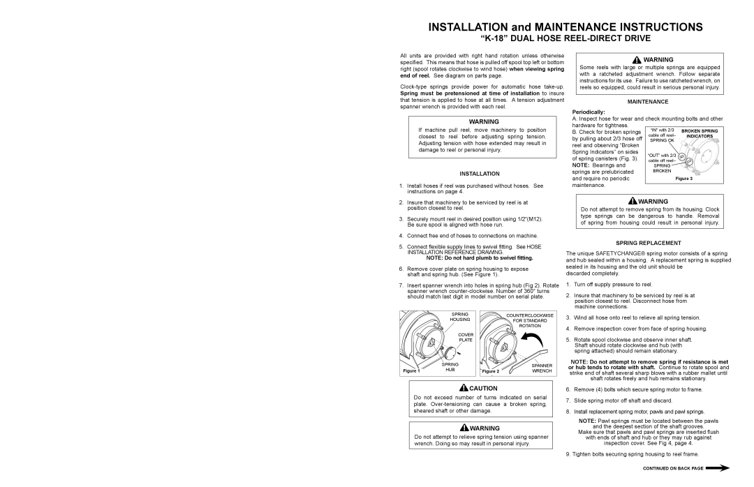
B. Check for broken springs
by pulling about 2/3 hose off reel and observing “Broken Spring Indicators” on sides of spring canisters (Fig. 3). NOTE: Bearings and springs are prelubricated
and require no periodic maintenance.
2.Insure that machinery to be serviced by reel is at position closest to reel.
3.Securely mount reel in desired position using 1/2"(M12). Be sure spool is aligned with hose run.
4.Connect free end of hoses to connections on machine.
5.Connect flexible supply lines to swivel fitting. See HOSE INSTALLATION REFERENCE DRAWING.
NOTE: Do not hard plumb to swivel fitting.
6.Remove cover plate on spring housing to expose shaft and spring hub. (See Figure 1).
![]() WARNING
WARNING
Do not attempt to remove spring from its housing. Clock type springs can be dangerous to handle. Removal of spring from housing could result in personal injury.
SPRING REPLACEMENT
The unique SAFETYCHANGE® spring motor consists of a spring and hub sealed within a housing. A replacement spring is supplied sealed in its housing and the old unit should be
discarded completely.
7.Insert spanner wrench into holes in spring hub (Fig 2). Rotate spanner wrench
1. | Turn off supply pressure to reel. |
2. | Insure that machinery to be serviced by reel is at |
| position closest to reel. Disconnect hose from |
| machine connections. |
| SPRING |
| HOUSING |
| COVER |
| PLATE |
| SPRING |
Figure 1 | HUB |
| COUNTERCLOCKWISE |
| FOR STANDARD |
| ROTATION |
| SPANNER |
Figure 2 | WRENCH |
3. | Wind all hose onto reel to relieve all spring tension. |
4. | Remove inspection cover from face of spring housing. |
5. | Rotate spool clockwise and observe inner shaft. |
| Shaft should rotate clockwise and hub (with |
| spring attached) should remain stationary. |
NOTE: Do not attempt to remove spring if resistance is met or hub tends to rotate with shaft. Continue to rotate spool and strike end of shaft several sharp blows with a rubber mallet until shaft rotates freely and hub remains stationary.
![]() CAUTION
CAUTION
Do not exceed number of turns indicated on serial plate.
![]() WARNING
WARNING
Do not attempt to relieve spring tension using spanner wrench. Doing so may result in personal injury.
6.Remove (4) bolts which secure spring motor to frame.
7.Slide spring motor off shaft and discard.
8.Install replacement spring motor, pawls and pawl springs.
NOTE: Pawl springs must be located between the pawls
and the deepest section of the shaft grooves.
Make sure that pawls and pawl springs are inserted flush
with ends of shaft and hub or they may rub against
inspection cover. See Fig 4, page 4. 9. Tighten bolts securing spring housing to reel frame.
CONTINUED ON BACK PAGE ![]()