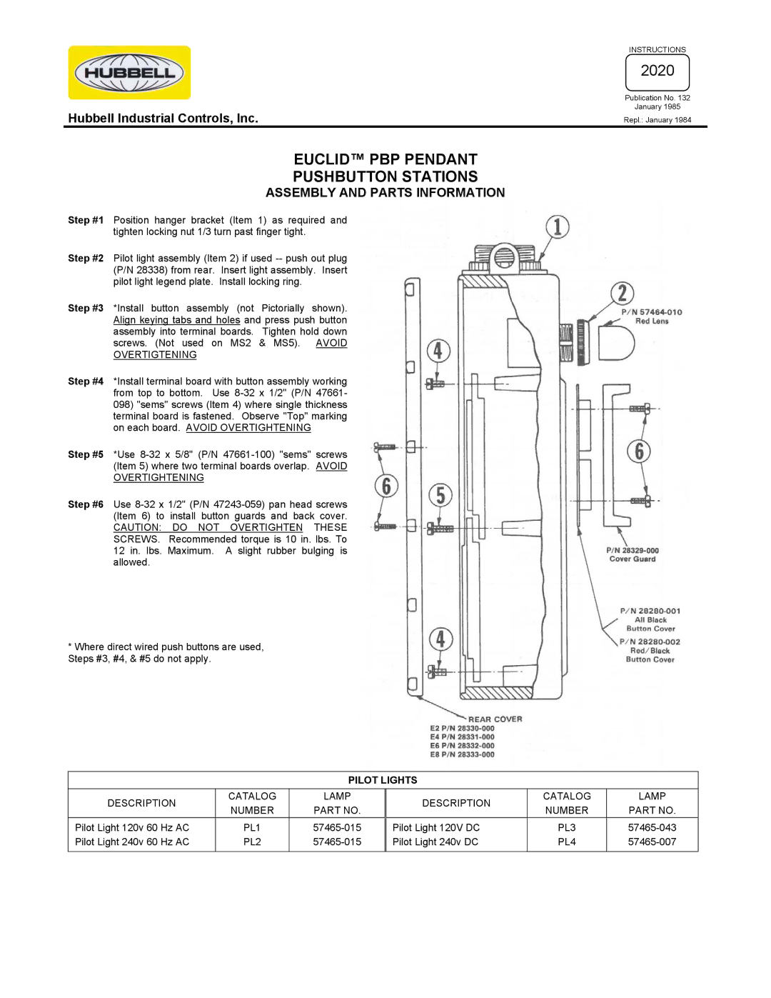
PBP Pendant specifications
The Hubbell PBP Pendant is an advanced lighting solution that combines innovative technology with practical design, making it an excellent choice for various commercial and industrial applications. This pendant light is engineered to deliver exceptional performance while maintaining energy efficiency and durability.One of the standout features of the Hubbell PBP Pendant is its robust construction. Crafted from high-quality materials, it is designed to withstand the rigors of demanding environments. The fixture's housing is typically made from aluminum or other durable metals, ensuring it can handle the stresses of everyday use without compromising on quality.
The PBP Pendant incorporates advanced LED technology, which not only provides bright and clear illumination but also significantly reduces energy consumption compared to traditional lighting solutions. LED fixtures are known for their long life spans, often exceeding 50,000 hours, which translates to lower maintenance costs and reduced frequency of replacements.
Versatility is another key characteristic of the Hubbell PBP Pendant. The fixture is available in various sizes, wattages, and lumen outputs, allowing it to be tailored to the specific needs of any space. Whether it’s a large warehouse, a retail environment, or a workshop, the PBP Pendant can be adapted to meet varying illumination requirements. It is also compatible with a range of mounting options, including chain, cable, or pendant mounting, offering flexibility for installation.
The PBP Pendant features advanced optics that maximize light distribution and minimize glare. This ensures that workspaces are illuminated evenly, enhancing safety and productivity in environments where precision is crucial. Additionally, the fixture can be equipped with various control options, including occupancy sensors and dimming capabilities, further optimizing energy efficiency while providing the right level of light when needed.
Moreover, the Hubbell PBP Pendant is designed with aesthetics in mind. Its sleek, modern appearance allows it to seamlessly integrate into various architectural styles, making it an attractive option for both functional and decorative lighting.
In conclusion, the Hubbell PBP Pendant is a versatile and reliable lighting solution that excels in performance, efficiency, and design. With its durable construction, advanced LED technology, flexible mounting options, and aesthetic appeal, it stands out as a go-to choice for anyone seeking high-quality pendant lighting in a commercial or industrial setting.

