Page
Warranty
Conventions
T e
Page
Contents
Page
Preventive Maintenance
Functional Overview
Removal and Replacement
Troubleshooting
Parts and Diagrams
Duplexer
LaserJet 5/5M/5N Printer
Page
Contents-10
Printer Features
Product Information
Product Family Information
Product Family Compatibility Matrix
Identification
CodeMeaning
Printer Identification Label for the HP LaserJet 4/4M
Specifications
Printer Dimensions
Power Specifications
HP LaserJet 4 and 4 Plus
Electrical Specifications
Environmental Specifications
Related Documentation
Printer Documentation
HP LaserJet 4 Documents-Description Part Number
HP LaserJet 4 Plus Documents-Description Part Number
Product and Laser Safety
Safety Information
U t i o n
FCC RFI Statement
Laser Statement Sweden/Finland
Laserturvallisuus Luokan 1 Laserlaite
Toner Safety
Ozone Statement
Technical Assistance HP Asap 1-800-333-1917 U.S
Doing Business with HP
HP FIRST, Europe
HP CompuServe Forum
Customer Information Centers
Customer Support Center Assist Line
Printer Drivers
European Customer Support Center
Other Areas
Site Planning Requirements
Site Requirements
Printer Space Requirements
Space Requirements
Media Specifications for MP Tray Tray
Print Media Specifications
Media Specifications for PC Tray Tray
Media Specifications for Duplex Assembly HP
Media Specifications for Optional LC Tray Tray
LaserJet 4 Plus, 4M Plus, 5, 5M, and 5N printers
Adhesive Labels
Label Construction
Overhead Transparencies
Envelopes
Specifications for Envelopes
Specifications
Dimensions
Envelope Construction
Site Planning and Requirements
Configuration
Introduction
See Appendix B for LaserJet 5 information
Using The Control Panel
Control Panel Keys
Indicator Lights
Indicator Mode Description
Control Panel Key Functions
Key Function
Reset Menu
Reset Menu Functions
Control Panel Menus
Control Panel Map
Printer Menu Items
Options Explanation
PCL Menu Items
Job Menu Items
Configuration Menu Items
Memory Configuration Items
Parallel Menu Items
Serial Menu Items
Test Menu Items
Printer Features
Protection HP LaserJet 4 only
Resource Saving HP LaserJet 4 Plus and 5 only
Buffering HP LaserJet 4 Plus and 5 only
Resolution Enhancement REt
EconoMode HP LaserJet 4 Plus and 5 only
Density
Remote Control Panel DOS
Select Use Password from the Printer Passwords box
Network Security
HP LaserJet Utility Macintosh
HP JetAdmin Utility Novell Networks
EC %-12345X@PJL JOB PASSWORD=numeric password
Select Lock Printer Control Panel
Ascii PJL Escape Sequence
Service Mode
Refer to Appendix B for LaserJet 5 information
Setting the Page Count
Setting the Cold Reset Default
Cold Reset
Understanding the PCL Self Test Printout
Self Test Printout Items for the HP LaserJet 4/4M
HP LaserJet 4/4M PCL Self Test Printout
Self Test Printout Items HP LaserJet 4 Plus/4M
Plus
HP LaserJet 4 Plus/4M Plus PCL Self Test Printout
Changing the Control Panel Display Language
Test Print Button
Test Print Button Location
Test Print Pattern
MS-DOS System Configuration
System Configuration
Parallel DOS Commands
Serial MS-DOS Commands
Serial Configuration
Printer I/O Configuration
Parallel Menu
Pacing Handshaking
Serial Cable Pin-outs
DB-9 RS-232 Serial Connection HP LaserJet
C2932A Cable Pinout for 9 to 9 Pin Connector
DB-25 RS-232 Serial Connection HP LaserJet 4 Plus/5
17255D Cable Pinout for 25 to 25 Pin Connector
DB-25 Serial Connection HP LaserJet
10 C2933A Cable Pinout for 9 to 25 Pin Connector
RS-422A Serial Configuration LaserJet 4 only
11 RS-422A Cable Pinout
Modular I/O Configuration
How to Obtain Printer Drivers
Install Printer Drivers and Utilities
Printer Drivers
DOS Utilities
Packing Checklist
Packing the Printer
Repackaging Instructions
Canada
Installing The Optional Lower Cassette
12 Installing the Printer on the Lower Cassette
14 Adjust the cassette for the paper size you want to load
13 Pull the cassette tray straight out of the printer
Configuration
Exec
20 Slide the cassette back into the Lower Cassette assembly
Envelope Feeder Installation
21 Remove the Black Plastic Cover
LaserJet 4 and 4 Plus
LaserJet
Simm Installation
Protecting the Simm Board
23 Identifying the Four Simm Slots
Memory Requirements
PCL Only PostScript Only Resolution 300 dpi 600 dpi
12Minimum Memory Recommendations LaserJet 4 Only
HP LaserJet 4/4M
Simm boards
HP LaserJet 4+/4M+/5/5M/5N
Accessing the Simm Slots
Installing the Simm Boards
25 Installing the Simm Board
Memory Simm
Testing a Simm Board
Running a Self Test Printout
Personality Simm PostScript
Troubleshooting a Simm Board
Service / Error Messages
Configuration
Preventive Maintenance
Selected Service Consumables
Life Expectancy of Consumables
Service Checkpoints
Maintenance Checkpoints
Cleaning Your Printer
Toner Cartridge
Saving Toner with EconoMode HP LaserJet 4 Plus and 5 Only
Storing the Toner Cartridge
Installing the Toner Cartridge
Removing the Toner Cartridge Sealing Tape
Inserting the Toner Cartridge
Non-HP Toner Cartridges
Clearing the Toner LOW Message
Periodic Maintenance Procedures
Removing the MP Tray Tray 1 Pickup Roller
Removing the MP Tray Tray 1 Separation Pad
Removing the PC Tray 2 Pickup Roller
Removing the Lower Cassette LC or Tray 3 Pickup Roller
Removing the Lower Cassette Pickup Roller
Removing and Replacing the Transfer Roller
Replacing the Transfer Roller
Removing the Transfer Roller
Replacing the Transfer Roller
Functional Overview
DC Controller System
DC Controller Loads
DC Controller Loads
Serial Data Communication
Serial Data Flow
Solenoids
Solenoid Signals
Solenoid Description
Photosensors
LJ 4 / 4 Plus
Photosensor Signals
Sensor Description
Microswitches
Microswitch Signals
Switch Description
Switch Settings for PC Tray 2 and LC Tray
PC Tray 2 and LC Tray 3 Tray Size Sensing System
Motors
Motors
Paper Jam Detection
Motors Description
Formatter System
Control
Formatter PCA-Functional Areas
Memory Management
Data Processing
PJL Overview
Image Formation System
Image Formation System
Photosensitive Drum
Drum Sensitivity
Cleaning Stage
Drum Cleaning Station
Conditioning Stage
Primary Charging Roller
Writing Stage
11 Drum Signals
Developing Stage
12 Image Development
13 Developing Potentials
Transferring Stage
14 Transfer of the Toner Image and Paper Separation
Fusing Stage
15 Fusing the Toner to the Paper
Paper Feed System
16 Input Paper Feed System Diagram
17 Paper Feed Assembly Sectional View Part Description
Printing from the MP Tray Tray
18 MP Tray Tray 1 to Output Tray Paper Path
Printing from the PC Tray Tray
Power System
20 Power System Block Diagram
Basic Sequence of Operation
Standard Printer Operation
Timing Diagrams
21 MP Tray Timing Diagram-HP LaserJet 4/4M
This a 2 panel pull-out
Warmup Period
PowerSave
Standby Period
Initial Rotation Period
Page
Print Period
Page
Last Rotation Period
Removal and Replacement
U t i o n T e
Hardware Review
Required Tools
Required Tools
Printer Hardware Descriptions
Drawing Description Purpose
Right Side Cover Removal
Removing the Covers
LJ 4/4 Plus
Top Cover Removal
Front Top Cover Screws and Latches
Control Panel Cable
Left Side Cover Removal
Left Side Cover Latches
Rear Door Removal
Releasing the Door Support
7a Releasing the Door Hinge LaserJet 4/5
Font Door Cover Removal LJ 5 Right Front Cover Removal
Font Door Removal LaserJet 4 shown
Font Door Cover Latches
Multi-Purpose MP Tray Tray 1 Door Removal
10 Removing the MP Tray Door
Multi-Purpose MP Tray Tray 1 Removal
11 Remove the Crossmember Bracket
12 Rotate the Tray Down to Release the Hinge from its Slots
Power Supply Removal
Assemblies Removal
13b Remove the Sheet Metal Plate LaserJet 4 Plus/5
15 6-wire and 3-wire Connectors for the Power Supply
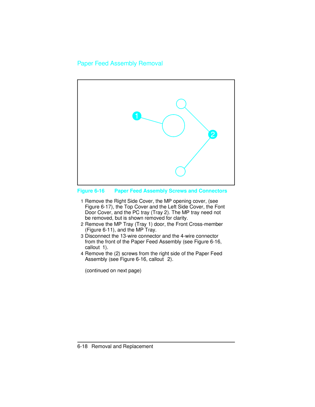
Paper Feed Assembly Removal
16 Paper Feed Assembly Screws and Connectors
17 MP Tray Opening Cover
18 Paper Feed Assembly Screws numbered
High Voltage Power Supply Hvps Removal
19 Hvps Screws 2 and Latches 2 Bottom View
Fuser Assembly Removal
U t i o n
Control Panel and Overlay Removal
21 Control Panel Latches
22 Changing the Control Panel Overlay
Removing the SIMMs Door
LaserJet
23b Opening the SIMMs Door LaserJet 4 Plus
LaserJet 4 Plus/5
Formatter Cage Removal
24a Formatter Cage Screws Right Side View LaserJet 4 T e
24b Formatter Cage Screws Right Side View LaserJet 4 Plus
Formatter PCA Removal
LaserJet 4 Formatter PCA
25a Formatter Cover and PCA Mounting Screws LaserJet
25b Interface Connector Support Screws LaserJet T e
LaserJet 4 Plus and 5 Formatter PCA
Interface Connector Support Screws LaserJet
Plus
27a DC Controller Connectors/Retaining Clips LaserJet T e
DC Controller Removal
Removal and Replacement
DC Controller Installation
28 Leading Edge Registration Adjustment Dimensions
Main Motor Assembly Removal
30 Main Motor Assembly
Gear Assembly Removal
31 Gear Assembly Screws Located behind Main Motor
Fan Connector
Fan Removal
33 Exhaust Fan Removal Laser Jet 4 shown
Output Assembly Removal
34 Output Assembly Removal
Paper Exit Sensor PS3 Removal
Exit Sensor
Scanner Assembly Removal
36 Scanner Assembly Removal
Lower Cassette Assemblies
Lower Cassette Sensor PCA Removal
Lower Cassette Pickup Motor Removal
38 Lower Cassette Upper Front Cover
39 Lower Cassette Motor
Replacing Fuser Assembly Parts
Fuser Assembly
Fuser Assembly Configuration
Fuser Assembly Configuration
Removing the Fuser Roller Heat Lamp
41 Fuser End Cap Removal LaserJet 4 only
42 Fuser Wire Harness Cover Removal LaserJet
42b Fuser Cover End Latches LaserJet 4 Plus
43 Left Side Fuser Cover
Gear Side Heat Lamp Connector
Bushing on the left side of the Fusing Roller
Wires in the gear cover slots
Fuser Gear Cap Removal
Fuser Assembly Thermoswitch Removal
46 Fuser Thermoswitch Connectors
47 Thermistor Connector
Thermistor Removal
48a Upper Fuser Frame Removal LaserJet
48b Upper Fuser Frame Removal LaserJet 4 Plus
Paper Control PCA Removal
49 Paper Control PCA Retaining Screws and Latches
Sensor PCA Removal
50 Sensor PCA Removal
PS1 and PS2 Sensor Assembly Removal
51 Removing the PS1/PS2 Sensor Assembly
High Voltage Contact Plate Hvcp and Paper Guide Removal
52 Guide Plate Cover Screw
53 Paper Guide Rollers
54 Cross Member Screws
55 Left Toner Cartridge Guide Plate Screw
56 High Voltage Contact and Feed Guide Assembly Latches
57 Orientation of Hvcp and Left Guide Plate
Interconnect PCA Removal
58 Right Side PC tray Rail Cover printer on right side
59 Interconnect PCA latches and AC Connector Mounting Pins
60 Correct Orientation of AC Connector Notch at Upper Left
Removal and Replacement
LaserJet 5 Error Map
Message on LJ 5/5M/5N Recommendations
LaserJet 5 Error Map
LaserJet 5 Error Map 7-C
LaserJet 5 Error Map
Pre-Troubleshooting Procedures
Preliminary Operating Checks
Printer Message Troubleshooting
Message Symptoms and Recommendations
Printer Message Summary Table
Printer Messages
Returns all printer settings to Printing Menu settings,
This message is displayed when the MIO AUX IO card is
For serial/Bi-Tronics parallel configuration, the computer
Refer to the Product Family Compatibility
Indicates a communications problem between the DC
Printer identified an internal service error. If this error
An error state. To clear this message, remove
Clearable Warnings
Clearable Warning Messages
Meaning
Printer Message Troubleshooting Procedures
Blank Display
Blank Display
Checks Action
MP/PC/LC Tray 1/2/3 Load Message
MP/PC/LC Tray 1/2/3 Load Message Checks
Figures 7-14 and 7-15 for locations
Cassette Size Switches SW603, SW604, SW605 Functional Check
PC Tray Size Sensing Microswitches Location
Switch Logic for Cassette Size
Paper Size Sensing Lower Cassette
PC Empty Sensor PS2 Functional Check
PS4 Check MP Tray Empty Sensor
Printer Open Message
Printer Open Checks
SW601 Functional Check
Location of the Top Cover Closed SW601 Actuator
Paper JAM Message
PS1 and PS3 Paper Path Sensors & PS5 Paper End Sensor
Paper Jam Troubleshooting Checklist
Jam Location Checks and Action Required
PS1 Input/Registration Sensor Check
PS1 Input/Registration Sensor
PS3 Exit Sensor Check
Pickup Motor Functional Test M2
Lower Cassette Functional Check
No EP Cart Message
Toner Low Message
Callout Assembly
Toner Cartridge Components
Error Message
Error Checks
Error Message Recommended Action
Service Error Fuser Malfunction
Service Fuser Malfunction Checks
Fuser Assembly Connector
1151 Error Beam Detect Checks
Error Scanner Malfunction
Laser/Scanner Assembly Functional Checks
57 or 57.1 Service Message Main Motor Failure
Main Motor Functional Checks
58 or 57.2 Service Fan Failure
Image Defect Summary
Image Defect Summary
Image Defect Summary
Possible Cause Action
Black Pages
Any Faint Print Condition
Faulty Registration
Right-Hand Image Missing
Small Print Voids
Random Horizontal Black Lines
Vertical White Streaks
Repetitive Defects
Smeared Print/Improper Fusing
Distorted Print
22Black Pages with Horizontal White Strips
Image Skew
Improperly Sized Image
PS5 Check MP Tray Paper End Sensor Functional Test
PS5 Test Sheet
Vertical Dark Streaks
Large Print Voids
LaserJet Family Paper Specifications
Background Scatter
White or Blank Pages
Image Formation Troubleshooting
Half Self-Test Functional Check
Drum Rotation Functional Check
High Voltage Power Supply Assembly
29High Voltage System Checks
Communications Check
Interface Troubleshooting
Test Message
Parallel DOS Commands
AUTOEXEC.BAT Standard Configurations
Serial MS-DOS Commands
Communications Checks
Communications Checks
HP LaserJet printers are not designed to work
MIO Troubleshooting
Troubleshooting Hints
Explanation of Self Test Printout
10 MIO Staus Information on the Self Test Printout
Troubleshooting Aids
Component Locations
12 Major Assembly and Connector Locations 2 Number Part
13 Major Assembly and Connector Locations 3 Number
Switch Locations
15 Optional 500 Sheet Lower Cassette Number Part
16 DC Controller PCA Layout-LaserJet 4/4M Number Part
17 DC Controller PCA Layout -LaserJet 4 Plus/5 Number Part
High Voltage PCA Layout
Number Part
Repetitive Defect Template
19 Repetitive Defect Ruler
20 Main Wiring Diagram LJ 4+/5 only
Voltage Test Points
Measuring the DC Voltage Levels
TB 201Voltages
Color Pin Number
Troubleshooting
Parts and Diagrams
How To Use the Parts Lists
Parts Lists and Illustrations
1a Field-Replaceable Assemblies 1
1b Field-Replaceable Assemblies 2
Field-Replaceable Assemblies
Exchng # Description
Field-Replaceable Assemblies
Covers and Panels
Covers and Panels
3a Top Cover Assembly for LaserJet 4/4+
Top Cover Assembly
Cable, Display Panel
3b Top Cover Assembly for LaserJet
Overlay Language
4a Internal Components 1
4aInternal Components Section
RB1-2111-030CN Shutter, arm RB1-2114-000CN
4b Internal Components 2
Lnternal Components Section
4c Internal Components 3
Internal Components Section
C2038-60004 LJ4+ C3919-67901
4d Internal Components 4
RB1-2251-000CN Block, Connecting RG5-0521-000CN
Main Switch Assembly
Main Switch Assembly
6a Paper Feed Assembly 1
6b Paper Feed Assembly 2
Paper Feed Assembly
MP Tray Tray 1 Assembly
MP Tray Tray 1 Assembly
Paper Output Assembly
Paper Output Assembly
Delivery Sensor Assembly
Delivery Sensor Assembly
10 Fuser Assembly
Fuser Assembly
RS5-0232-000CN
Accessory Parts
11 Lower Cassette Base Assembly
Lower Cassette Base Assembly
Lower Cassette Drive Assembly
Lower Cassette Drive Assembly
13 Lower Cassette Assembly
13Lower Cassette Assembly
14 Universal Cassette
Simm Memory
Universal Cassette
Simm Modules
Miscellaneous Parts and Accessories
Miscellaneous Parts and Accessories
Parts List
Alphanumeric Parts List
PCA
Parts and Diagrams
Parts and Diagrams
Parts and Diagrams
Parts and Diagrams
Parts and Diagrams
Parts and Diagrams
C2084C +/5
Parts and Diagrams
Parts and Diagrams
Parts and Diagrams
Parts and Diagrams
Parts and Diagrams
Parts and Diagrams
Parts and Diagrams
Parts and Diagrams
Duplexer
Figure A-1 Duplexer Paper Path
Duplex Printing
Switchback Assembly
Holding Tray
Figure A-2 Duplexer Major Components
Figure A-3 Electrical Block Diagram
Electrical Overview
Installing the Optional Duplexer
LJ 4 +
Figure A-4 Duplexer Installation/Removal
Required Tools
Removal and Replacement
R n i n g U t i o n
Removing the Switchback Covers
Removing the Covers
Removing the Side Cover on Power Side
Figure A-6
Removing the Side Cover on Gear Side
Figure A-7 Side Cover on Gear Side
Figure A-8 Latch Location on Underside of Duplexer
Removing the Back Cover
Removing the Front Cover
Removing Internal Duplexer Components
Removing the Fan/Motor/Solenoid/Sensor
Removing the Switchback Paper Guide
Figure A-11 Switchback Paper Guide
Removing the Paper Guide Assembly
Figure A-12 Wire Routing and Upper Switchback Guide Screw
Removing the Paper Roller
Figure A-13 Solenoid Arm
Figure A-14 Upper Paper Guide Sheet Metal
Figure A-15 Gears on Paper Roller
Removing the Control PCA
Figure A-16
Figure A-17 Control PCA
Removing the Power PCA
Figure A-18 Power PCA
Figure A-19 Plate on Power PCA Side of Duplexer
Removing the Holding Tray Center Paper Guide
Removing the Holding Tray Belt
Figure A-20 Holding Tray Belt Cover Plate
Figure A-21 Holding Tray Gears and Belt
Removing the Holding Tray Paper Sensor
Figure A-22 Holding Tray Paper Sensor
Removing the Switchback Assembly
Figure A-23 Switchback Assembly Hinge Pins
Parts and Diagrams for the Duplexer
Figure A-24 Duplex External Covers
Table A-24 Duplex External Covers Description
Figure A-25a Duplex Feeder Assembly 1
Figure A-25b Duplex Feeder Assembly 2
Table A-25 Duplex Feed Assembly Description
RF1-3817-00017
Figure A-26a Duplex Switchback Assembly 1
Figure A-26b Duplex Switchback Assembly 2
Table A-26 Duplex Switchback Assembly Description
Description
LaserJet 5/5M/5N Printer
Product Information
Table B-1
HP LJ4M+ HPLJ5 HPLJ5M HPLJ5N
Table B-2
LaserJet 4? LaserJet 4 Plus? LaserJet 5?
LaserJet 5/5M/5N Printer B-5
HP LaserJet 5 / 5M / 5N
Table B-3Printer Dimensions
Table B-4
Table B-6
Table B-5
Table B-7
HP LaserJet 5/5M/5N Part Number Documents-Description
Laser Statement Sweden/Finland
Control Panel Layout
Control Panel Keys
Table B-8 Control Panel Keys Explanation
Printer back on line
Key Explanation
Value +
To change a control panel setting
Figure B-3 Control Panel Menu Map
Printing Menu
TableB-10 Printing Menu Items
Media size
PCL Fonts Menu
Table B-11 PCL Fonts Menu Items
PostScript Menu
Job Menu
Table B-12 PostScript Menu Items
Table B-13 Job Menu Items
Configuration Menu
Table B-14 Configuration Menu Items
Auto OFF
Memory Configuration Menu
Table B-15 Memory Configuration Menu Items
Table B-16 Parallel Menu Items
Serial Menu
Table B-17 Serial Menu Items
Resets Menu
Table B-18 Resets Menu Items
Test Menu
Table B-19 Test Menu Items
LaserJet 5/5M/5N Printer B-25
Service Mode
Setting the Cold Reset Default
Skip Demo
Diagnostics
Big Data
Programming a Flash Simm
Changing the Control Panel Display Language
Nvram Init
Table B-20 Self Test Printout Items for the HP LaserJet
Figure B-4 HP LaserJet 5 PCL Self Test Printout
Infrared Communication
Figure B-5 IR Data Flow
System Requirements
To Print Using the Infrared Port
Figure B-6 IrDA Port Location
Figure B-7 IrDa Port Ranges
Troubleshooting IR Printing Problems
Figure B-8 Infrared Test Tool
Page
Table B-21 Solutions for Infrared Not Responding Situation
Infrared Port Not Responding
Situation Solution
Index
Index-1
Index-2
Index-3
Index-4
Index-5
Index-6
Index-7
Index-8
SN-1 Service Notes
SN-2 Service Notes
SN-3 Service Notes
SN-4 Service Notes
SN-5 Service Notes
SN-6 Service Notes
SN-7 Service Notes
SN-8 Service Notes
C3916-90984