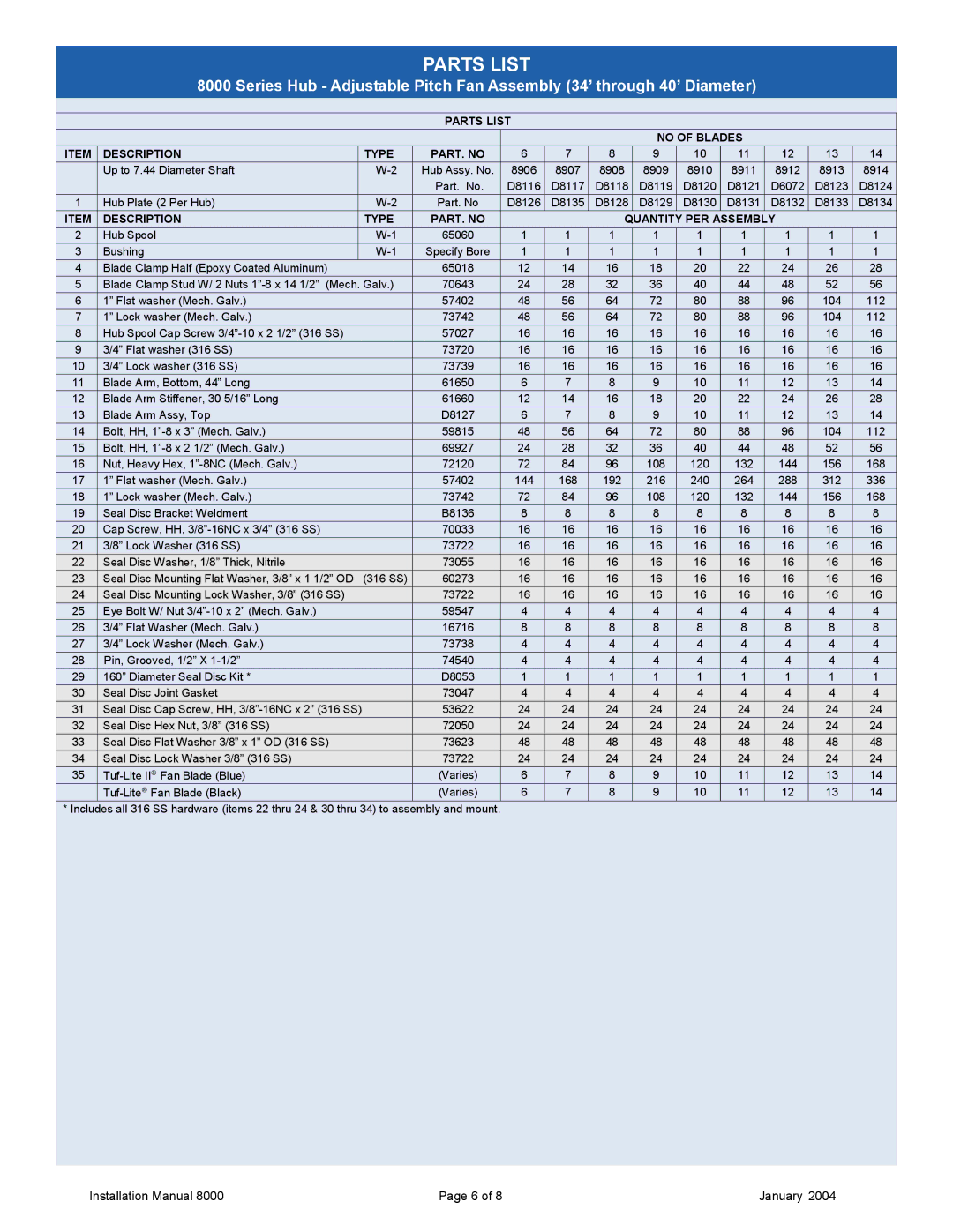
8000 specifications
Hudson Industries has made a significant impact in the tech world with its innovative product, the Hudson Industries 8000. This cutting-edge device is designed to cater to a wide range of users, from professionals to tech enthusiasts, offering unparalleled performance and versatility.One of the standout features of the Hudson Industries 8000 is its powerful processing capabilities. Equipped with the latest generation multi-core processor, it ensures seamless multitasking and lightning-fast responsiveness. This makes the device perfect for demanding applications such as graphic design, video editing, and complex data analysis.
In addition to its robust processing power, the Hudson Industries 8000 boasts an advanced graphics engine. This technology provides stunning visuals, making it an ideal choice for gamers and creatives alike. Whether you're playing the latest AAA titles or working on intricate 3D models, the graphics engine delivers crisp, vibrant imagery that enhances every experience.
Storage and memory options are also a highlight of the Hudson Industries 8000. The device offers a range of SSD configurations, providing speedy data access and ample space for all your files and applications. With options for up to 1TB of SSD storage and 32GB of high-speed RAM, users can enjoy rapid loading times and efficient operation, even under heavy workloads.
Another key characteristic of the Hudson Industries 8000 is its versatility in connectivity. The device comes equipped with multiple USB ports, an HDMI output, and support for the latest wireless standards, including Wi-Fi 6. This ensures that users can easily connect to a variety of peripherals and networks, enhancing productivity and flexibility.
The design of the Hudson Industries 8000 is sleek and modern, prioritizing both aesthetics and functionality. Its compact size makes it highly portable, allowing users to take their work on the go without sacrificing performance. The high-resolution display offers exceptional clarity and color reproduction, providing an immersive experience whether you're working or unwinding with multimedia content.
Security features are also a top priority with the Hudson Industries 8000. Built-in biometric authentication and advanced encryption technology ensure that your data remains protected from unauthorized access, giving users peace of mind in today's increasingly digital landscape.
In summary, the Hudson Industries 8000 stands out with its powerful performance, advanced graphics capabilities, ample storage options, versatile connectivity, sleek design, and robust security features. Whether for professional use or personal enjoyment, it is a comprehensive device that meets the demands of a modern tech-savvy audience.

