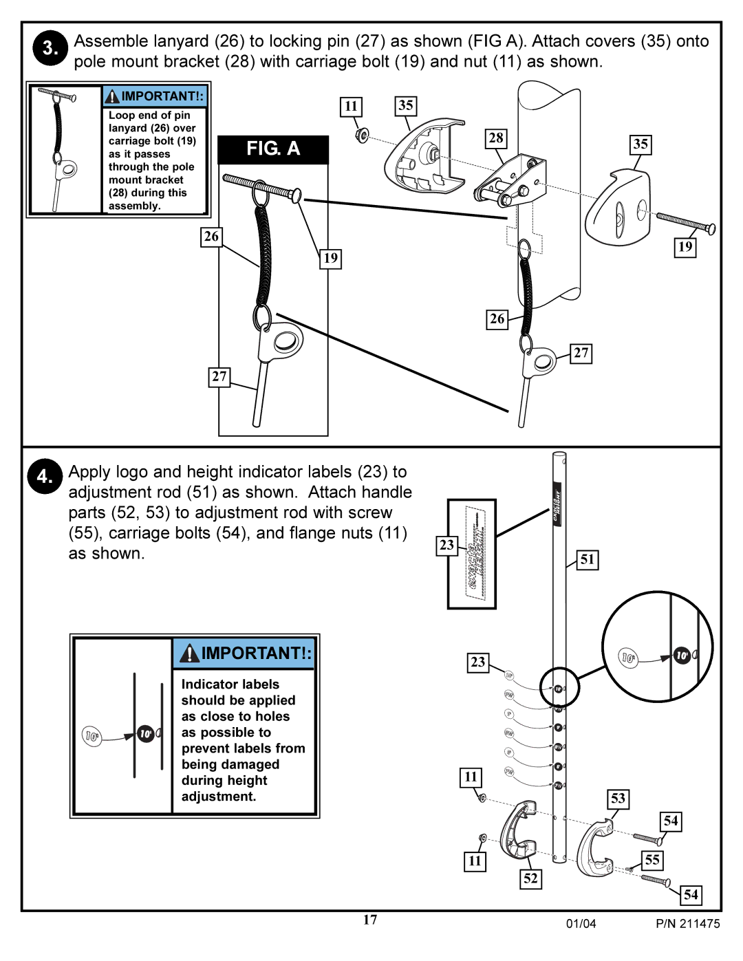
3. Assemble lanyard (26) to locking pin (27) as shown (FIG A). Attach covers (35) onto pole mount bracket (28) with carriage bolt (19) and nut (11) as shown.
![]() IMPORTANT!:
IMPORTANT!:
Loop end of pin lanyard (26) over carriage bolt (19) as it passes through the pole mount bracket
(28)during this assembly.
26
FIG. A
19
11
35
28
26
35
19
27
![]()
![]() 27
27
4. Apply logo and height indicator labels (23) to adjustment rod (51) as shown. Attach handle parts (52, 53) to adjustment rod with screw (55), carriage bolts (54), and flange nuts (11) as shown.
![]() IMPORTANT!:
IMPORTANT!:
Indicator labels should be applied as close to holes as possible to prevent labels from being damaged during height adjustment.
23 |
23
11
11
52
51
53
54
55
![]() 54
54
17 | 01/04 | P/N 211475 |