STB Connections
 Front & Rear Panel


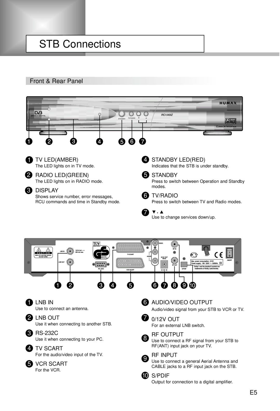
1 TV LED(AMBER) | 4 STANDBY LED(RED) |
The LED lights on in TV mode. | Indicates that the STB is under standby. |
2RADIO LED(GREEN)
The LED lights on in RADIO mode.
3DISPLAY
Shows service number, error messages, RCU commands and time in Standby mode.
5STANDBY
Press to switch between Operation and Standby modes.
6TV/RADIO
Press to switch between TV and Radio modes.
7 ![]() ,
, ![]()
Use to change services down/up.
1 LNB IN | 6 AUDIO/VIDEO OUTPUT |
Use to connect an antenna.
Audio/video signal from your STB to VCR or TV.
2LNB OUT
Use it when connecting to another STB.
3RS-232C
Use it when connecting to your PC.
4TV SCART
For the audio/video input of the TV.
5VCR SCART
For the VCR.
70/12V OUT
For an external LNB switch.
8 | RF OUTPUT |
Use to connect a RF signal from your STB to | |
| RF(ANT) input jack on your TV. |
9 | RF INPUT |
| Use to connect a general Aerial Antenna and |
| CABLE jacks to a RF input jack on the STB. |
10 | S/PDIF |
| Output for connection to a digital amplifier. |
E5