1.2 Front Panel
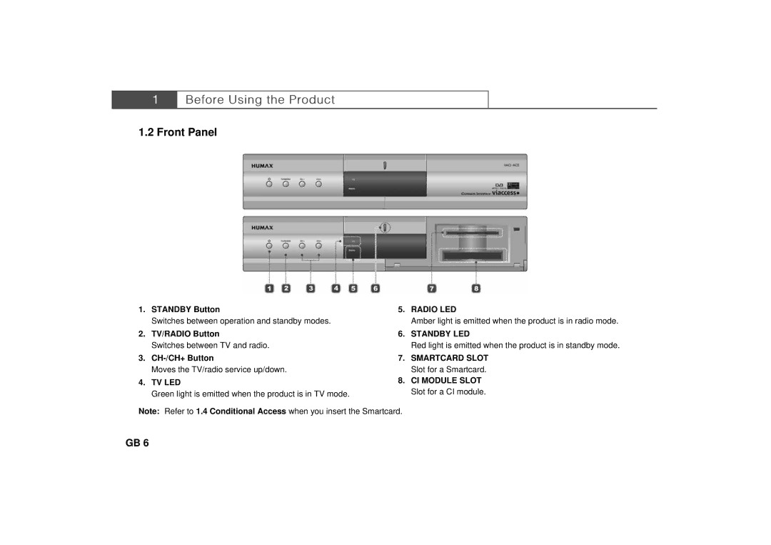
1. | STANDBY Button | 5. | RADIO LED | |
| ** |
| ** | |
| Switches between operation and standby modes. |
| Amber light is emitted when the product is in radio mode. | |
| ** |
| ** | |
2. | TV/RADIO Button | 6. | STANDBY LED | |
| ** |
| ** | |
| Switches between TV and radio. |
| Red light is emitted when the product is in standby mode. | |
| ** |
| ** | |
3. | 7. | SMARTCARD SLOT | ||
| ** |
| ** | |
| Moves the TV/radio service up/down. |
| Slot for a Smartcard. | |
| ** | 8. | CI MODULE SLOT | |
4. | TV LED | |||
| ** | |||
| ** |
| Slot for a CI module. | |
| Green light is emitted when the product is in TV mode. |
|
**
Note: Refer to 1.4 Conditional Access when you insert the Smartcard.
GB 6