3
Unit Switch |
| |
|
| |
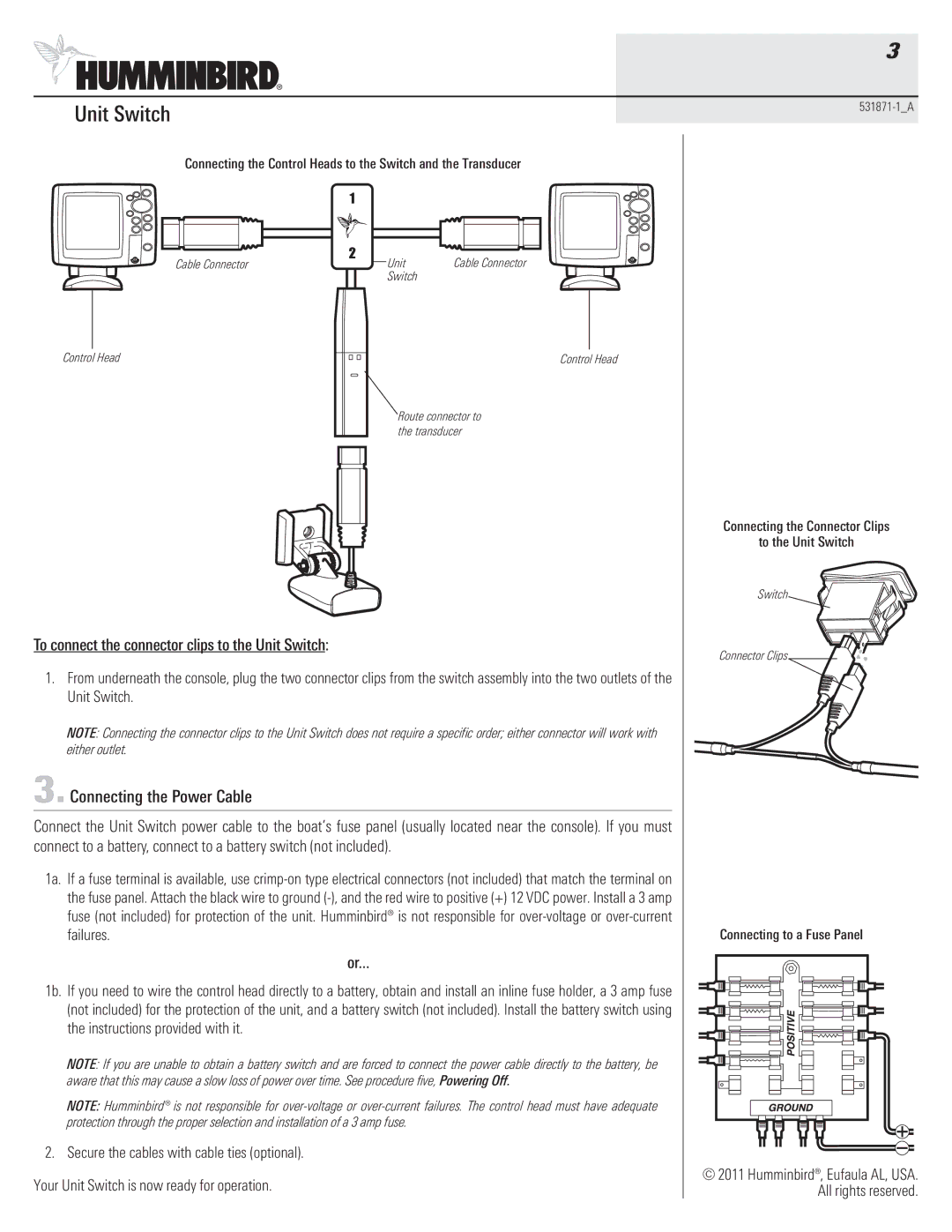
Connecting the Control Heads to the Switch and the Transducer | ||
| 1 |
|
Cable Connector | 2 | Cable Connector |
Unit | ||
| Switch |
|
|
|
|
|
|
|
|
|
|
|
|
|
|
|
|
|
Control Head |
|
| Control Head | ||||
|
| ||||||
Route connector to the transducer
|
| Connecting the Connector Clips | |
|
| to the Unit Switch | |
|
| Switch | |
To connect the connector clips to the Unit Switch: | Connector Clips | ||
|
| ||
1. | From underneath the console, plug the two connector clips from the switch assembly into the two outlets of the |
| |
| Unit Switch. |
| |
| NOTE: Connecting the connector clips to the Unit Switch does not require a specific order; either connector will work with |
| |
| either outlet. |
| |
3. Connecting the Power Cable |
| ||
Connect the Unit Switch power cable to the boat’s fuse panel (usually located near the console). If you must |
| ||
connect to a battery, connect to a battery switch (not included). |
| ||
1a. | If a fuse terminal is available, use |
| |
| the fuse panel. Attach the black wire to ground |
| |
| fuse (not included) for protection of the unit. Humminbird® is not responsible for |
| |
| failures. | Connecting to a Fuse Panel | |
| or... |
| |
1b. | If you need to wire the control head directly to a battery, obtain and install an inline fuse holder, a 3 amp fuse |
| |
| (not included) for the protection of the unit, and a battery switch (not included). Install the battery switch using |
| |
| the instructions provided with it. |
| |
| NOTE: If you are unable to obtain a battery switch and are forced to connect the power cable directly to the battery, be |
| |
| aware that this may cause a slow loss of power over time. See procedure five, Powering Off. |
| |
| NOTE: Humminbird® is not responsible for |
| |
| protection through the proper selection and installation of a 3 amp fuse. |
| |
2. | Secure the cables with cable ties (optional). |
| |
Your Unit Switch is now ready for operation. | © 2011 Humminbird®, Eufaula AL, USA. | ||
All rights reserved. | |||
|
| ||