Step 6: Final Wiring

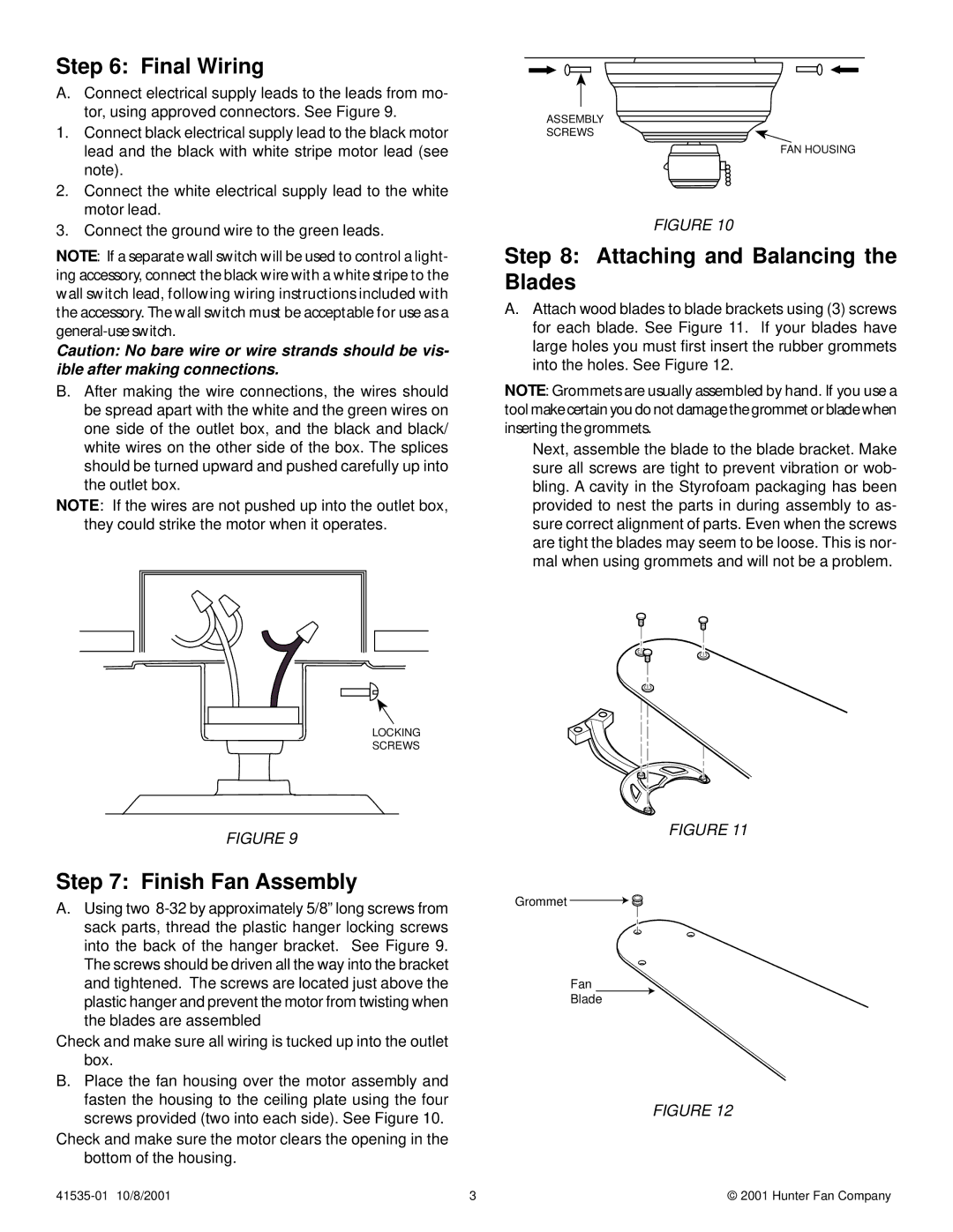
A.Connect electrical supply leads to the leads from mo- tor, using approved connectors. See Figure 9.

1.Connect black electrical supply lead to the black motor lead and the black with white stripe motor lead (see note).

2.Connect the white electrical supply lead to the white motor lead.

3.Connect the ground wire to the green leads.

NOTE: If a separate wall switch will be used to control a light- ing accessory, connect the black wire with a white stripe to the wall switch lead, following wiring instructions included with the accessory. The wall switch must be acceptable for use as a general-use switch.

Caution: No bare wire or wire strands should be vis- ible after making connections.

B.After making the wire connections, the wires should be spread apart with the white and the green wires on one side of the outlet box, and the black and black/ white wires on the other side of the box. The splices should be turned upward and pushed carefully up into the outlet box.

NOTE: If the wires are not pushed up into the outlet box, they could strike the motor when it operates.

ASSEMBLY

SCREWS

FAN HOUSING

FIGURE 10

Step 8: Attaching and Balancing the Blades

A.Attach wood blades to blade brackets using (3) screws for each blade. See Figure 11. If your blades have large holes you must first insert the rubber grommets into the holes. See Figure 12.

NOTE: Grommets are usually assembled by hand. If you use a tool make certain you do not damage the grommet or blade when inserting the grommets.

Next, assemble the blade to the blade bracket. Make sure all screws are tight to prevent vibration or wob- bling. A cavity in the Styrofoam packaging has been provided to nest the parts in during assembly to as- sure correct alignment of parts. Even when the screws are tight the blades may seem to be loose. This is nor- mal when using grommets and will not be a problem.

LOCKING SCREWS

FIGURE 9

Step 7: Finish Fan Assembly

A.Using two 8-32 by approximately 5/8” long screws from sack parts, thread the plastic hanger locking screws into the back of the hanger bracket. See Figure 9. The screws should be driven all the way into the bracket and tightened. The screws are located just above the plastic hanger and prevent the motor from twisting when the blades are assembled

Check and make sure all wiring is tucked up into the outlet box.

B.Place the fan housing over the motor assembly and fasten the housing to the ceiling plate using the four screws provided (two into each side). See Figure 10.

Check and make sure the motor clears the opening in the bottom of the housing.

FIGURE 11

Grommet

Fan

Blade

FIGURE 12

41535-01 10/8/2001

3

© 2001 Hunter Fan Company

Page 3
Image 3
Hunter Fan 41535-01 installation instructions Final Wiring, Attaching and Balancing the Blades, Finish Fan Assembly

41535-01 specifications

The Hunter Fan 41535-01, a standout model in the realm of ceiling fans, is designed with functionality and style in mind. This fan offers a harmonious blend of contemporary aesthetics with advanced technology, making it an ideal choice for modern living spaces.

One of the primary features of the Hunter Fan 41535-01 is its powerful motor, which ensures an optimal airflow distribution throughout the room. The WhisperWind motor technology guarantees a quiet operation while efficiently circulating air, allowing you to enjoy a comfortable environment without the distracting noise often associated with traditional fans. This feature is particularly valuable in home settings where tranquility is a priority.

The design of the 41535-01 is both versatile and chic, featuring a sleek profile that seamlessly fits in various interior decors. It is well-equipped with a stylish finish, which enhances its visual appeal, making it a perfect addition to any room, from living spaces to bedrooms or home offices. Moreover, the fan's blades are designed to maximize air movement, with an aesthetic that complements the fan's overall design.

Another remarkable feature of this ceiling fan is its adaptability. The fan is designed to accommodate both manual and remote-controlled operation. This flexibility allows users to adjust settings from the comfort of their seating area, making it highly convenient. The fan also includes various speed settings, enabling homeowners to customize airflow according to their preferences.

Additionally, the Hunter Fan 41535-01 is optimized for energy efficiency, making it an eco-friendly choice. By using a ceiling fan regularly, you can reduce reliance on air conditioning, ultimately leading to lower energy bills and a smaller carbon footprint. The durable construction and quality materials ensure longevity, providing a reliable cooling solution for years to come.

In summary, the Hunter Fan 41535-01 exemplifies the ideal combination of modern style, innovative technology, and practical features. With its quiet operation, aesthetic design, remote control capability, and energy-efficient performance, this ceiling fan represents a smart investment for enhancing comfort and style in contemporary homes. Whether you're looking to improve airflow or elevate your interior design, the Hunter Fan 41535-01 meets the needs of modern consumers with ease.