B.Remove the screws from the motor hub. Insert one of these screws in hole in blade bracket. Use a screw- driver to hold in place. Align blade holes with mounting holes in hub, by turning screw and readjusting blade bracket until screw mates with threaded hole in hub. Do not tighten until both screws have been put in blade bracket. Repeat for all blades. See Figure 13.

C.A blade balancing kit has been provided with your fan. Should the fan wobble in operation, you may use this kit to correct the balance per the instructions supplied with the kit.

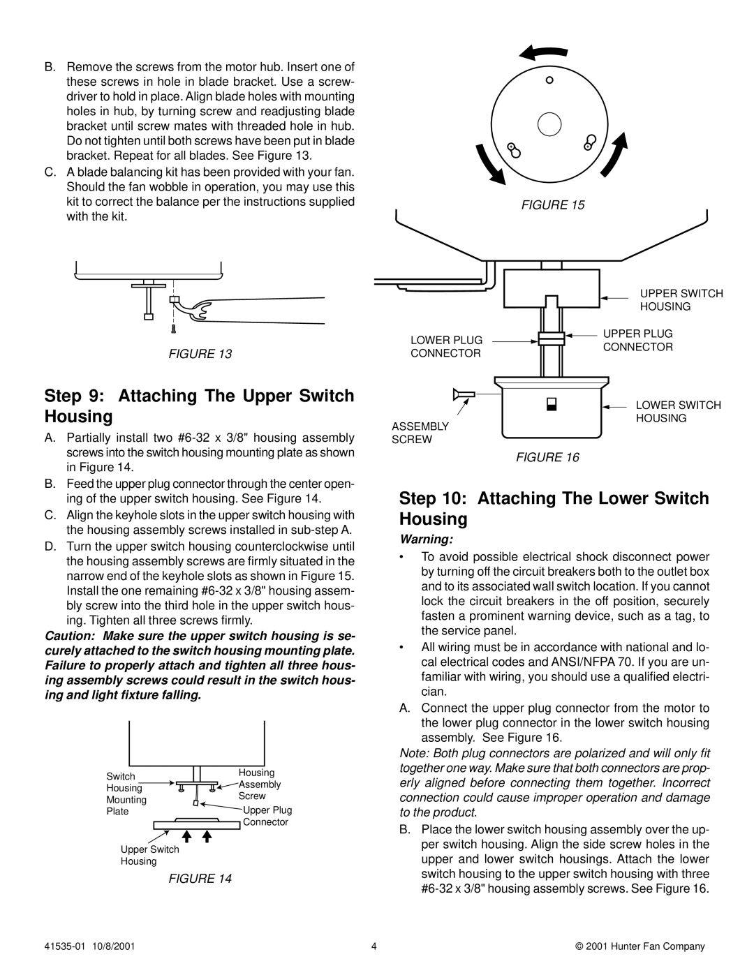
FIGURE 15

FIGURE 13

Step 9: Attaching The Upper Switch Housing

A. Partially install two #6-32 x 3/8" housing assembly

screws into the switch housing mounting plate as shown

LOWER PLUG CONNECTOR

ASSEMBLY

SCREW

UPPER SWITCH

HOUSING

UPPER PLUG

CONNECTOR

LOWER SWITCH

HOUSING

in Figure 14.

B. Feed the upper plug connector through the center open-

ing of the upper switch housing. See Figure 14.

C. Align the keyhole slots in the upper switch housing with

the housing assembly screws installed in sub-step A.

D. Turn the upper switch housing counterclockwise until

the housing assembly screws are firmly situated in the

narrow end of the keyhole slots as shown in Figure 15.

Install the one remaining #6-32 x 3/8" housing assem-

bly screw into the third hole in the upper switch hous-

ing. Tighten all three screws firmly.

Caution: Make sure the upper switch housing is se- curely attached to the switch housing mounting plate. Failure to properly attach and tighten all three hous- ing assembly screws could result in the switch hous- ing and light fixture falling.

Switch

Housing

Assembly

Housing


Mounting

Screw

Plate


Upper Plug


Connector

Upper Switch

Housing

FIGURE 14

FIGURE 16

Step 10: Attaching The Lower Switch Housing

Warning:

To avoid possible electrical shock disconnect power by turning off the circuit breakers both to the outlet box and to its associated wall switch location. If you cannot lock the circuit breakers in the off position, securely fasten a prominent warning device, such as a tag, to the service panel.

All wiring must be in accordance with national and lo- cal electrical codes and ANSI/NFPA 70. If you are un- familiar with wiring, you should use a qualified electri- cian.

A.Connect the upper plug connector from the motor to the lower plug connector in the lower switch housing assembly. See Figure 16.

Note: Both plug connectors are polarized and will only fit together one way. Make sure that both connectors are prop- erly aligned before connecting them together. Incorrect connection could cause improper operation and damage to the product.

B.Place the lower switch housing assembly over the up- per switch housing. Align the side screw holes in the upper and lower switch housings. Attach the lower switch housing to the upper switch housing with three #6-32 x 3/8" housing assembly screws. See Figure 16.

41535-01 10/8/2001

4

© 2001 Hunter Fan Company

Page 4
Image 4
Hunter Fan 41535-01 installation instructions Attaching The Upper Switch Housing, Attaching The Lower Switch Housing

41535-01 specifications

The Hunter Fan 41535-01, a standout model in the realm of ceiling fans, is designed with functionality and style in mind. This fan offers a harmonious blend of contemporary aesthetics with advanced technology, making it an ideal choice for modern living spaces.

One of the primary features of the Hunter Fan 41535-01 is its powerful motor, which ensures an optimal airflow distribution throughout the room. The WhisperWind motor technology guarantees a quiet operation while efficiently circulating air, allowing you to enjoy a comfortable environment without the distracting noise often associated with traditional fans. This feature is particularly valuable in home settings where tranquility is a priority.

The design of the 41535-01 is both versatile and chic, featuring a sleek profile that seamlessly fits in various interior decors. It is well-equipped with a stylish finish, which enhances its visual appeal, making it a perfect addition to any room, from living spaces to bedrooms or home offices. Moreover, the fan's blades are designed to maximize air movement, with an aesthetic that complements the fan's overall design.

Another remarkable feature of this ceiling fan is its adaptability. The fan is designed to accommodate both manual and remote-controlled operation. This flexibility allows users to adjust settings from the comfort of their seating area, making it highly convenient. The fan also includes various speed settings, enabling homeowners to customize airflow according to their preferences.

Additionally, the Hunter Fan 41535-01 is optimized for energy efficiency, making it an eco-friendly choice. By using a ceiling fan regularly, you can reduce reliance on air conditioning, ultimately leading to lower energy bills and a smaller carbon footprint. The durable construction and quality materials ensure longevity, providing a reliable cooling solution for years to come.

In summary, the Hunter Fan 41535-01 exemplifies the ideal combination of modern style, innovative technology, and practical features. With its quiet operation, aesthetic design, remote control capability, and energy-efficient performance, this ceiling fan represents a smart investment for enhancing comfort and style in contemporary homes. Whether you're looking to improve airflow or elevate your interior design, the Hunter Fan 41535-01 meets the needs of modern consumers with ease.