![]() CAUTION: To avoid possible electrical shock, before installing your fan, disconnect the power by turning off the circuit breakers to the outlet box and associated wall switch location. If you cannot lock the circuit breakers in the off position, securely fasten a prominent warning device, such as a tag, to the service panel.
CAUTION: To avoid possible electrical shock, before installing your fan, disconnect the power by turning off the circuit breakers to the outlet box and associated wall switch location. If you cannot lock the circuit breakers in the off position, securely fasten a prominent warning device, such as a tag, to the service panel.
Note: e isolators should be flush against the ceiling.
Tighten the screws into the 9/64” pilot holes; do not use lubricants on the screws. Do not over tighten.
![]() Flat Washer
Flat Washer
3” Wood Screw
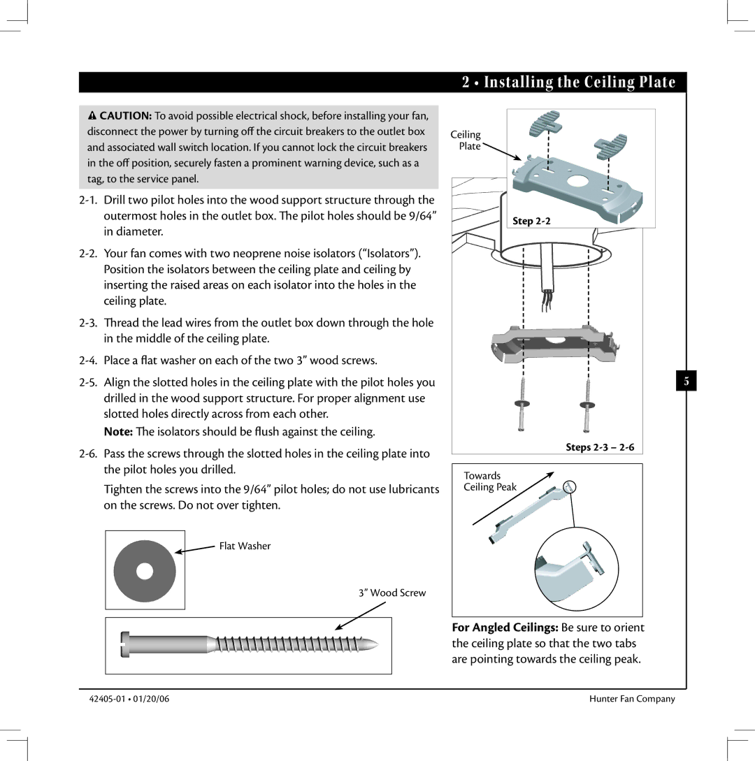
2 • Installing the Ceiling Plate
Ceiling
Plate ![]()
Step 2-2
5
Steps 2-3 – 2-6
Towards
Ceiling Peak
For Angled Ceilings: Be sure to orient the ceiling plate so that the two tabs are pointing towards the ceiling peak.
Hunter Fan Company |