
42700 specifications
The Hunter Fan 42700 is a striking blend of style, efficiency, and technology, making it a standout choice for those looking to enhance their living spaces with a ceiling fan that not only cools but also elevates decor. This model epitomizes Hunter's dedication to quality craftsmanship and innovative features.One of the main features of the Hunter Fan 42700 is its sleek, modern design that complements a variety of interior styles. Available in multiple finishes, it allows homeowners to choose the perfect match for their room’s aesthetic. The fan blades are designed for optimal air movement and are crafted from durable materials, ensuring longevity and performance.
In terms of performance, the Hunter Fan 42700 boasts a powerful motor that provides efficient airflow while maintaining whisper-quiet operation. This feature is particularly advantageous for bedrooms and living areas where noise disruption can be a concern. The fan’s three-speed settings allow users to customize their comfort level depending on the time of year or personal preference.
Another standout technology integrated into the Hunter Fan 42700 is its energy-efficient operation. It is designed to consume less electricity compared to traditional ceiling fans, helping homeowners save on energy bills while contributing to environmental sustainability. This aligns with the growing preference for eco-friendly home appliances.
Additionally, the Hunter Fan 42700 includes a reversible motor, enabling users to change the direction of the blades. This feature provides versatility, allowing the fan to circulate warm air during the winter months and cool air in the summer. Such adaptability makes it an all-season solution for climate control.
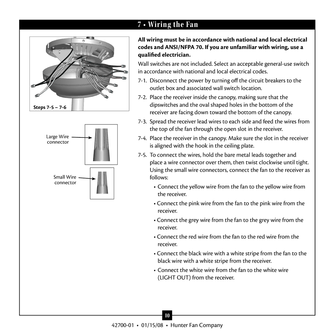
Installation and usage are also user-friendly, with the fan coming with comprehensive instructions for easy setup. Many models include a remote control, allowing for convenient operation from anywhere in the room, further enhancing the user experience.
With its combination of aesthetic appeal, advanced technology, and functional features, the Hunter Fan 42700 stands as an excellent investment for improving comfort in any home. Whether it’s for enhancing air circulation or adding a stylish focal point, this ceiling fan is sure to satisfy a wide range of homeowner needs.