Switch Housing
www.HunterFan.com
1.888.830.1326
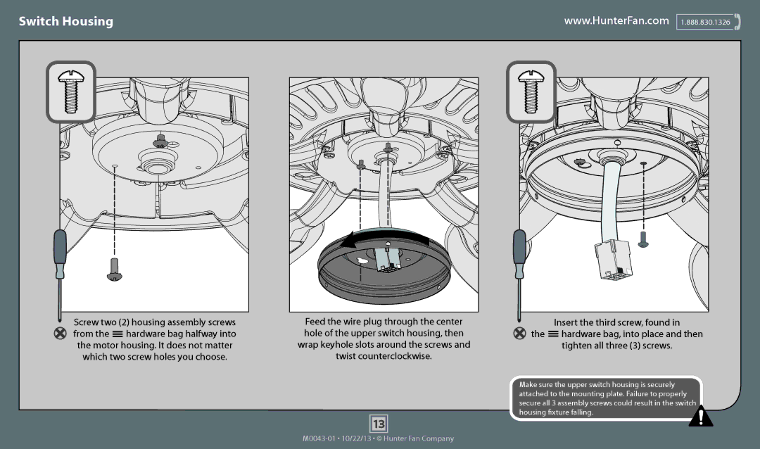
Screw two (2) housing assembly screws | Feed the wire plug through the center | ||
from the |
| hardware bag halfway into | hole of the upper switch housing, then |
| |||
| |||
the motor housing. It does not matter | wrap keyhole slots around the screws and | ||
which two screw holes you choose. | twist counterclockwise. | ||
13
Insert the third screw, found in
the ![]() hardware bag, into place and then
hardware bag, into place and then
tighten all three (3) screws.
Make sure the upper switch housing is securely attached to the mounting plate. Failure to properly secure all 3 assembly screws could result in the switch housing fixture falling.![]()