HSK1084HD_Manual_062805.qxd 10/21/05 7:22 PM Page 2
Stage Three —
The Automatic Float Charge feature is ideal for maintaining a battery. It automatically tops off battery as needed, keeping it fully charged all the time.
FEATURES
•This unit has three charge rate settings, accessed by the 2/6/10 AMP button:
a)2 amps: smaller batteries, as in lawn mowers, snowmobiles, motorcycles, etc.
b)6 amps:
c)10 amps: automobiles and light trucks
•Automatic float charge monitoring
•Microprocessor controlled for proper operation and fault detection.
•Large, lighted digital display shows charging current, codes that indicate faults, modes of operation and
•
•Rapid charging three stage output
•
•Connect to side or
•Rugged case, plus sturdy carry handle
•
•Ideal during winter season when vehicle's starting performance is reduced by cold or extreme weather conditions
•Single beep tone indicates a button is pressed or a mode change occurs
•Alternator check can determine if alternator output is within a typical voltage range
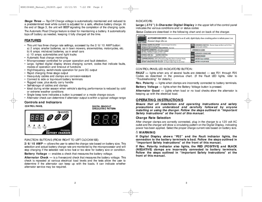
Controls and Indicators
CONTROL PANEL | DIGITAL READOUT |
| CIRCULATING PATTERN |
|
|
FUNCTION BUTTONS (FROM RIGHT TO LEFT CLOCKWISE):
2/6/10 AMP — allows the user to select the charge rate based on battery size. This selection and actual battery charge rate are monitored by the microprocessor and will stop charging if the selected rate is too fast or too slow for battery size or condition.
Battery Voltage — enables a check that measures the battery voltage.
Alternator Check — is a
INDICATORS:
Large (.375”)
Status Codes are described in the following chart and on back of the charger.
AC POWER INDICATOR - When connected to an AC outlet, digital display shows circulating pattern to indicate power is on. FAULT CODES Disconnect charger after use.
F01 | INTERNAL SHORTED CELL BATTERY - Cannot be charged. Have battery | F05 | OVERHEATED CONDITION - Disconnect charger and allow to cool for 30 min., |
| checked by certified auto service center. |
| check for ample ventilation. |
| EXCESSIVE LOAD ON BATTERY WHILE CHARGING - Check load. | OPERATION CODES | |
F02 | BAD BATTERY CONNECTION - Check battery connection. | ||
| BATTERY VOLTAGE TOO LOW TO ACCEPT CHARGE - |
|
|
| Have battery checked by certified auto service center. |
| ALTERNATOR VOLTAGE CHECK |
F03 | INTERNAL OPEN CELL/ SULFATED CONDITION - | 000 | CHARGER STANDBY |
| Have battery checked by certified auto service center. | ||
F04 | OVERTIME CONDITION - Battery will not accept a charge after 18 hours of continuous charging. | FUL | BATTERY FULLY CHARGED |
| Battery may have internal damage. Have battery chacked by certified auto service center. | FLO | BATTERY IN FLOAT MODE |
| BATTERY CHARGE RATE IS SET TOO LOW - Set charger to higher charge rate. See manual. | ||
CONTROL PANEL LED INDICATORS/BUTTON:
FAULT — lights when any of several faults are detected — see F01 through F05 Codes as described in the previous chart. (If the Fault LED lights, refer to “Troubleshooting” for details.)
Rev. Polarity — lights when clamps are incorrectly connected to battery terminals. Battery Voltage — lights when the Battery Voltage button is pressed.
Alternator Good — Lights when load or no load checks show the alternator is keeping up with the electrical load.
OPERATING INSTRUCTIONS
Ensure that all installation and operating instructions and safety precautions are understood and carefully followed by anyone installing or using the charger. Follow the steps outlined in “Important Safety Instructions” at the front of this manual.
Charge Rate Selection
After charger clamps are correctly connected, plug in the charger to a 120 volt AC outlet and the charger will show a circulating pattern on the Digital Display, indicating power has been applied. Select the proper charge current rate based on battery size.
![]() WARNING
WARNING
If Digital Display shows “F02” and the Fault indicator lights, the connection to the battery terminals is bad. Follow the steps outlined in “Important Safety Instructions” at the front of this manual.
If Rev. Polarity indicator also lights, the RED (POSITIVE) and BLACK (NEGATIVE) clamps are incorrectly connected to battery terminals. Follow the steps outlined in “Important Safety Instructions” at the front of this manual.
2 | 3 |