| ASSEMBLY |
| |
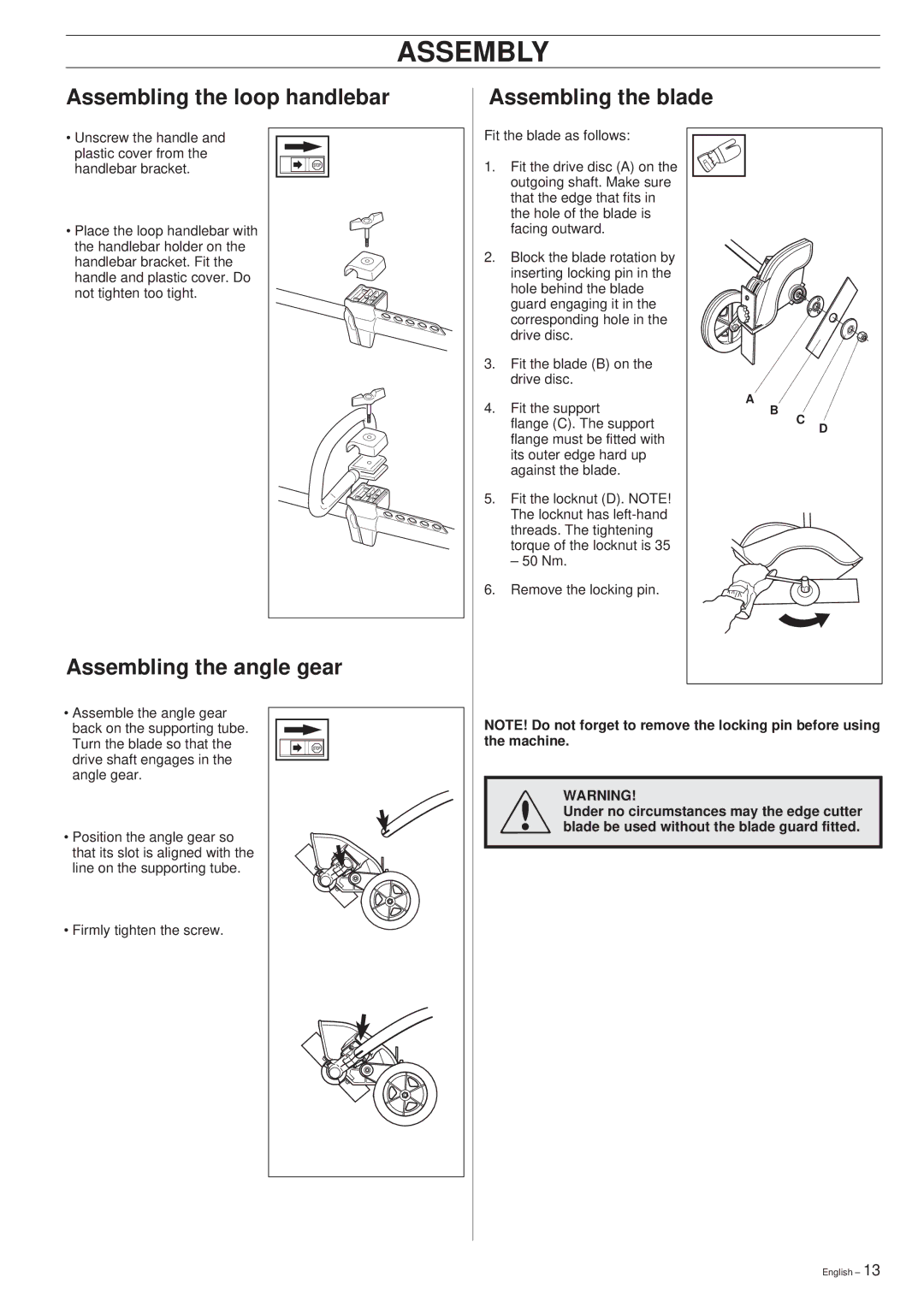
Assembling the loop handlebar | Assembling the blade |
| |
• Unscrew the handle and | Fit the blade as follows: |
| |
plastic cover from the | 1. Fit the drive disc (A) on the |
| |
handlebar bracket. |
| ||
|
| outgoing shaft. Make sure |
|
|
| that the edge that fits in |
|
|
| the hole of the blade is |
|
• Place the loop handlebar with |
| facing outward. |
|
the handlebar holder on the | 2. | Block the blade rotation by |
|
handlebar bracket. Fit the |
| ||
| inserting locking pin in the |
| |
handle and plastic cover. Do |
|
| |
| hole behind the blade |
| |
not tighten too tight. |
|
| |
| guard engaging it in the |
| |
|
|
| |
|
| corresponding hole in the |
|
|
| drive disc. |
|
| 3. Fit the blade (B) on the |
| |
|
| drive disc. |
|
| 4. | Fit the support | A |
| B | ||
|
| flange (C). The support | C |
|
| flange must be fitted with | D |
|
|
| |
|
| its outer edge hard up |
|
|
| against the blade. |
|
| 5. Fit the locknut (D). NOTE! |
| |
|
| The locknut has |
|
|
| threads. The tightening |
|
|
| torque of the locknut is 35 |
|
|
| – 50 Nm. |
|
| 6. | Remove the locking pin. |
|
Assembling the angle gear |
|
|
|
• Assemble the angle gear | NOTE! Do not forget to remove the locking pin before using | |
back on the supporting tube. | ||
Turn the blade so that the | the machine. | |
drive shaft engages in the |
|
|
angle gear. | ! |
|
| WARNING! | |
| Under no circumstances may the edge cutter | |
• Position the angle gear so | blade be used without the blade guard fitted. | |
| ||
that its slot is aligned with the |
|
|
line on the supporting tube. |
|
|
• Firmly tighten the screw.
English – 13