ASSEMBLY
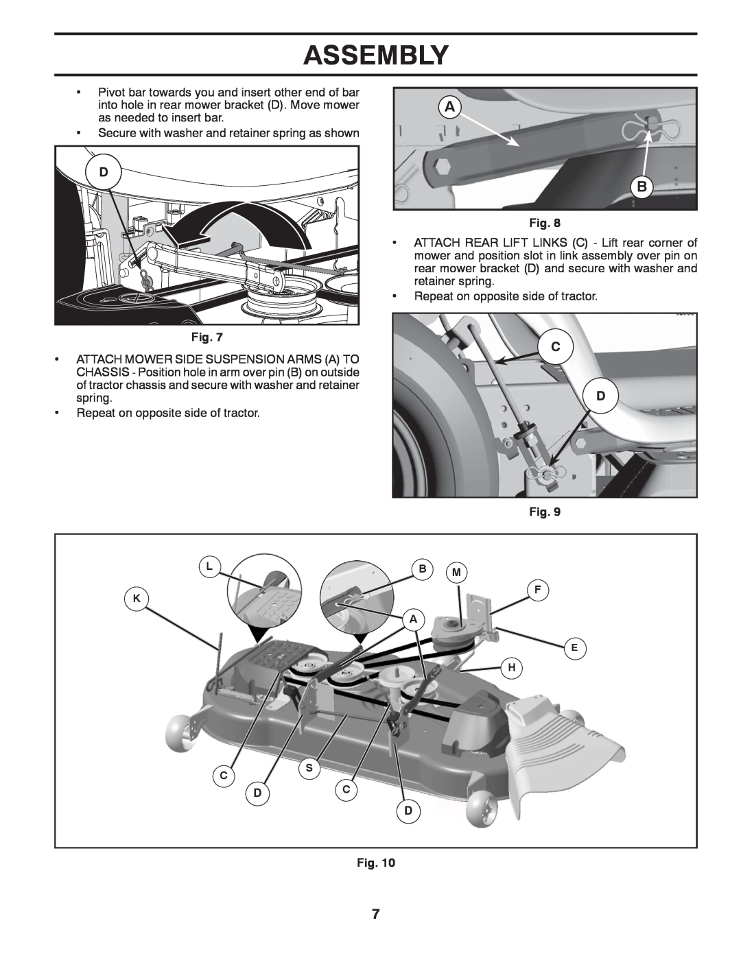
•Pivot bar towards you and insert other end of bar into hole in rear mower bracket (D). Move mower as needed to insert bar.
•Secure with washer and retainer spring as shown
D |
Fig. 7
•ATTACH MOWER SIDE SUSPENSION ARMS (A) TO CHASSIS - Position hole in arm over pin (B) on outside of tractor chassis and secure with washer and retainer spring.
•Repeat on opposite side of tractor.
A
B
Fig. 8
•ATTACH REAR LIFT LINKS (C) - Lift rear corner of mower and position slot in link assembly over pin on rear mower bracket (D) and secure with washer and retainer spring.
•Repeat on opposite side of tractor.
C
D
Fig. 9
LB M
K
F
![]() A
A
E
![]() H
H
CS
DC
D
Fig. 10
7