ASSEMBLY
Fitting the bevel gear
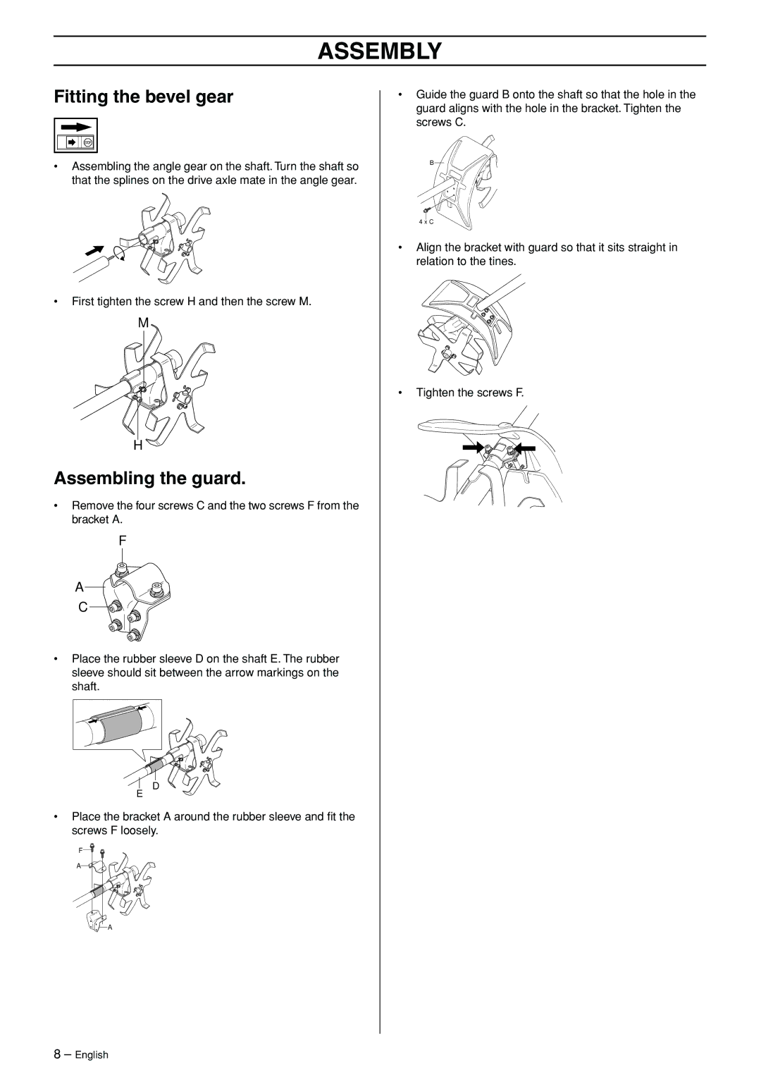
•Assembling the angle gear on the shaft. Turn the shaft so that the splines on the drive axle mate in the angle gear.
•First tighten the screw H and then the screw M.
M
H
Assembling the guard.
•Remove the four screws C and the two screws F from the bracket A.
F
A
C
•Place the rubber sleeve D on the shaft E. The rubber sleeve should sit between the arrow markings on the shaft.
•Guide the guard B onto the shaft so that the hole in the guard aligns with the hole in the bracket. Tighten the screws C.
B
4 x C
•Align the bracket with guard so that it sits straight in relation to the tines.
•Tighten the screws F.
E
D
•Place the bracket A around the rubber sleeve and fit the screws F loosely.
F![]()
A![]()
![]()
![]()
![]() A
A
8 – English