Section 2: Assembly
IMPORTANT: Left and right sides of the unit are determined from the operator position, facing the direction of forward travel.
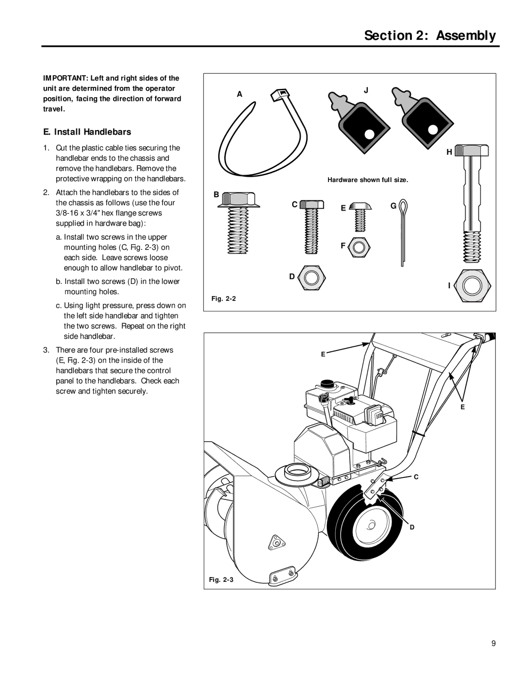
E. Install Handlebars
1.Cut the plastic cable ties securing the handlebar ends to the chassis and remove the handlebars. Remove the protective wrapping on the handlebars.
2.Attach the handlebars to the sides of the chassis as follows (use the four
a.Install two screws in the upper mounting holes (C, Fig.
b.Install two screws (D) in the lower mounting holes.
c.Using light pressure, press down on the left side handlebar and tighten the two screws. Repeat on the right side handlebar.
3.There are four
A |
| J |
|
| |
|
| H |
| Hardware shown full size. | |
B |
|
|
C | E | G |
| F |
|
D |
| I |
|
| |
Fig. |
|
|
| E |
|
|
| E |
|
| C |
|
| D |
Fig. |
|
|
9