Section 5: Maintenance
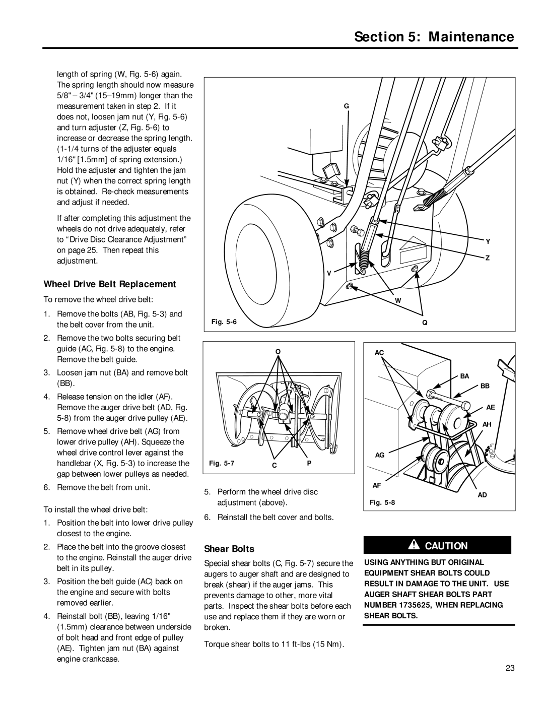
length of spring (W, Fig.
If after completing this adjustment the wheels do not drive adequately, refer to “Drive Disc Clearance Adjustment” on page 25. Then repeat this adjustment.
Wheel Drive Belt Replacement
To remove the wheel drive belt:
1.Remove the bolts (AB, Fig.
2.Remove the two bolts securing belt guide (AC, Fig.
3.Loosen jam nut (BA) and remove bolt (BB).
4.Release tension on the idler (AF). Remove the auger drive belt (AD, Fig.
5.Remove wheel drive belt (AG) from lower drive pulley (AH). Squeeze the wheel drive control lever against the handlebar (X, Fig.
6.Remove the belt from unit.
To install the wheel drive belt:
1. Position the belt into lower drive pulley |
closest to the engine. |
G
|
|
| Y |
|
|
| Z |
|
| V |
|
|
|
| W |
Fig. |
|
| Q |
| O |
| AC |
|
|
| BA |
|
|
| BB |
|
|
| AE |
|
|
| AH |
Fig. |
| P | AG |
C |
| ||
5. Perform the wheel drive disc | AF | ||
AD | |||
adjustment (above). |
| Fig. | |
6. Reinstall the belt cover and bolts. |
| ||
2. | Place the belt into the groove closest |
| to the engine. Reinstall the auger drive |
| belt in its pulley. |
3. | Position the belt guide (AC) back on |
| the engine and secure with bolts |
| removed earlier. |
4. | Reinstall bolt (BB), leaving 1/16" |
| (1.5mm) clearance between underside |
| of bolt head and front edge of pulley |
| (AE). Tighten jam nut (BA) against |
| engine crankcase. |
Shear Bolts
Special shear bolts (C, Fig.
Torque shear bolts to 11
CAUTION
USING ANYTHING BUT ORIGINAL EQUIPMENT SHEAR BOLTS COULD RESULT IN DAMAGE TO THE UNIT. USE AUGER SHAFT SHEAR BOLTS PART NUMBER 1735625, WHEN REPLACING SHEAR BOLTS.
23