Section 5: Maintenance
Lubrication
At the beginning and end of each season or after every 25 hours of operation, lubricate the unit as recommended below:
1.Lightly oil both the deflector chute cap pivot points (D, Fig.
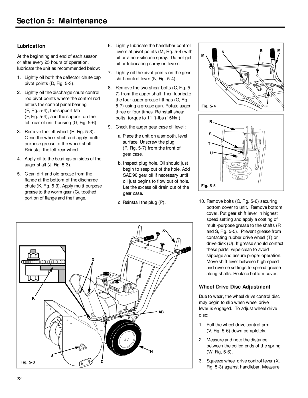
2.Lightly oil the discharge chute control rod pivot points where the control rod enters the control panel bearing
(E, Fig. 5-4), the support tab
(F, Fig. 5-4), and the support on the left rear of unit housing (G, Fig. 5-6).
3.Remove the left wheel (H, Fig. 5-3). Clean the wheel shaft and apply multi- purpose grease to the wheel shaft. Reinstall the left rear wheel.
4.Apply oil to the bearings on sides of the auger shaft (J, Fig.
5.Clean dirt and old grease from the flange at the bottom of the discharge chute (K, Fig.
6.Lightly lubricate the handlebar control levers at pivot points (M, Fig.
7.Lightly oil the pivot points on the gear shift control lever (N, Fig.
8.Remove the two shear bolts (C, Fig. 5-
7)from the auger shaft, then lubricate the four auger grease fittings (O, Fig.
9.Check the auger gear case oil level :
a.Place the unit on a smooth, level surface. Unscrew the plug
(P, Fig. 5-7) from the front of gear case.
b.Inspect plug hole. Oil should just begin to seep out of the hole. Add SAE 90 gear oil if necessary until oil just begins to flow out of hole. Let the excess oil drain out of the gear case.
c.Reinstall the plug (P).
N | E | M |
M |
|
|
Fig. |
| F |
R |
|
|
S |
|
|
T |
|
|
U |
|
|
Fig. |
|
|
10. Remove bolts (Q, Fig. |
bottom cover to unit. Remove bottom |
cover. Put gear shift lever in highest |
speed setting and apply a coating of |
| X |
| D |
K |
|
| AB |
| H |
| J |
Fig. | C |
22 |
|
and S, Fig. |
contacting rubber drive wheel (T) or |
drive disk (U). If grease should contact |
these parts, wipe clean to avoid |
slippage and assure proper operation. |
Move shift lever between high speed |
and reverse settings to spread grease |
along shafts. Replace bottom cover. |
Wheel Drive Disc Adjustment
Due to wear, the wheel drive control disc may begin to slip when wheel drive lever is engaged. To adjust wheel drive disc:
1.Pull the wheel drive control arm (V, Fig.
2.Measure and note the distance between the coiled ends of the spring (W, Fig,
3.Squeeze wheel drive control lever (X, Fig.