Section 2: Assembly
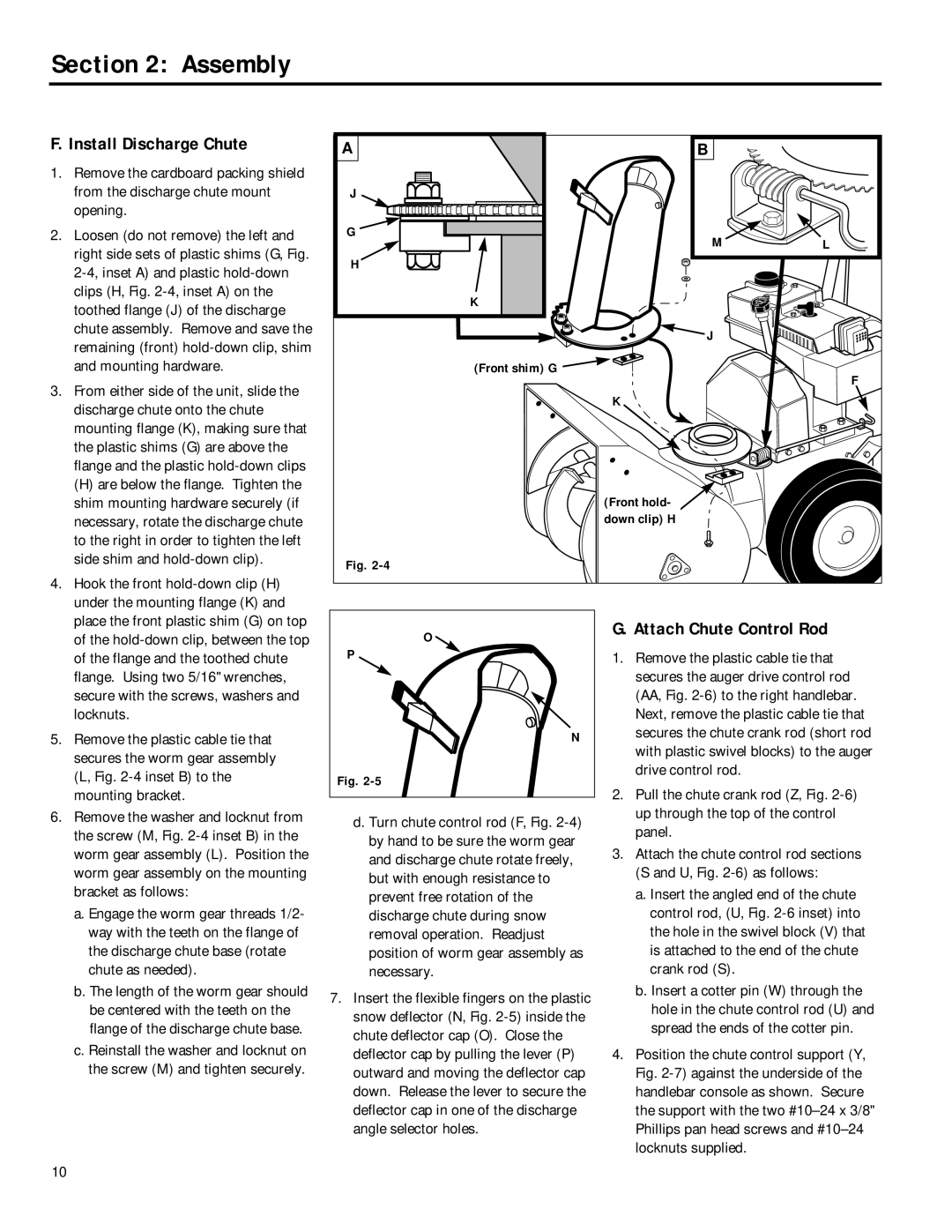
F. Install Discharge Chute
1. Remove the cardboard packing shield |
from the discharge chute mount |
opening. |
2. Loosen (do not remove) the left and |
right side sets of plastic shims (G, Fig. |
clips (H, Fig. |
toothed flange (J) of the discharge |
chute assembly. Remove and save the |
remaining (front) |
and mounting hardware. |
3. From either side of the unit, slide the |
discharge chute onto the chute |
mounting flange (K), making sure that |
the plastic shims (G) are above the |
flange and the plastic |
(H) are below the flange. Tighten the |
shim mounting hardware securely (if |
necessary, rotate the discharge chute |
to the right in order to tighten the left |
side shim and |
4. Hook the front |
under the mounting flange (K) and |
place the front plastic shim (G) on top |
A | B |
|
J |
|
|
G | M | L |
| ||
H |
|
|
| K |
|
| J |
|
| (Front shim) G | F |
|
| |
| K |
|
| (Front hold- |
|
| down clip) H |
|
Fig. |
|
|
of the |
of the flange and the toothed chute |
flange. Using two 5/16" wrenches, |
secure with the screws, washers and |
locknuts. |
5. Remove the plastic cable tie that |
secures the worm gear assembly |
(L, Fig. |
mounting bracket. |
6. Remove the washer and locknut from |
the screw (M, Fig. |
worm gear assembly (L). Position the |
worm gear assembly on the mounting |
bracket as follows: |
a. Engage the worm gear threads 1/2- |
way with the teeth on the flange of |
the discharge chute base (rotate |
chute as needed). |
b. The length of the worm gear should |
be centered with the teeth on the |
flange of the discharge chute base. |
c. Reinstall the washer and locknut on |
the screw (M) and tighten securely. |
O ![]()
P
N
Fig.
d. Turn chute control rod (F, Fig.
7.Insert the flexible fingers on the plastic snow deflector (N, Fig.
G. Attach Chute Control Rod
1.Remove the plastic cable tie that secures the auger drive control rod (AA, Fig.
2.Pull the chute crank rod (Z, Fig.
3.Attach the chute control rod sections (S and U, Fig.
a.Insert the angled end of the chute control rod, (U, Fig.
b.Insert a cotter pin (W) through the hole in the chute control rod (U) and spread the ends of the cotter pin.
4.Position the chute control support (Y, Fig.
10