Section 4: Operation
Auger drive engagement
WARNING
STOP THE ENGINE AND REMOVE THE SPARK PLUG WIRE FROM THE SPARK PLUG BEFORE REMOVING ANY DEBRIS FROM THE AUGER HOUSING.
1.Remove any debris from inside the auger housing.
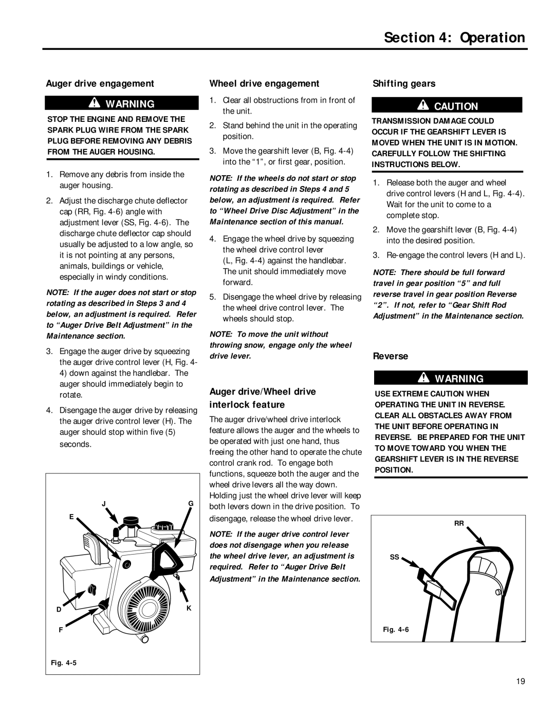
2.Adjust the discharge chute deflector cap (RR, Fig.
NOTE: If the auger does not start or stop rotating as described in Steps 3 and 4 below, an adjustment is required. Refer to “Auger Drive Belt Adjustment” in the Maintenance section.
3.Engage the auger drive by squeezing the auger drive control lever (H, Fig. 4- 4) down against the handlebar. The auger should immediately begin to rotate.
4.Disengage the auger drive by releasing the auger drive control lever (H). The auger should stop within five (5)
seconds. |
|
J | G |
E |
|
D | K |
F |
|
Fig. |
|
Wheel drive engagement
1.Clear all obstructions from in front of the unit.
2.Stand behind the unit in the operating position.
3.Move the gearshift lever (B, Fig.
NOTE: If the wheels do not start or stop rotating as described in Steps 4 and 5 below, an adjustment is required. Refer to “Wheel Drive Disc Adjustment” in the Maintenance section of this manual.
4.Engage the wheel drive by squeezing the wheel drive control lever
(L, Fig. 4-4) against the handlebar. The unit should immediately move forward.
5.Disengage the wheel drive by releasing the wheel drive control lever. The wheels should stop.
NOTE: To move the unit without throwing snow, engage only the wheel drive lever.
Auger drive/Wheel drive interlock feature
The auger drive/wheel drive interlock feature allows the auger and the wheels to be operated with just one hand, thus freeing the other hand to operate the chute control crank rod. To engage both functions, squeeze both the auger and the wheel drive levers all the way down. Holding just the wheel drive lever will keep both levers down in the drive position. To
disengage, release the wheel drive lever.
NOTE: If the auger drive control lever does not disengage when you release the wheel drive lever, an adjustment is required. Refer to “Auger Drive Belt Adjustment” in the Maintenance section.
Shifting gears
CAUTION
TRANSMISSION DAMAGE COULD OCCUR IF THE GEARSHIFT LEVER IS MOVED WHEN THE UNIT IS IN MOTION. CAREFULLY FOLLOW THE SHIFTING INSTRUCTIONS BELOW.
1.Release both the auger and wheel drive control levers (H and L, Fig.
2.Move the gearshift lever (B, Fig.
3.
NOTE: There should be full forward travel in gear position “5” and full reverse travel in gear position Reverse “2”. If not, refer to “Gear Shift Rod Adjustment” in the Maintenance section.
Reverse
WARNING
USE EXTREME CAUTION WHEN OPERATING THE UNIT IN REVERSE. CLEAR ALL OBSTACLES AWAY FROM THE UNIT BEFORE OPERATING IN REVERSE. BE PREPARED FOR THE UNIT TO MOVE TOWARD YOU WHEN THE GEARSHIFT LEVER IS IN THE REVERSE POSITION.
RR
SS
Fig.
19
