ASSEMBLY
CAUTION: ALWAYS WEAR SAFETY GLASSES OR EYE SHIELDS WHILE ASSEM- BLING TILLER/CULTIVATOR.
FIG. 1-OP on page 6 shows the tiller/cultivator completely assembled.
Reference to the right and left hand side of the tiller/cultivator is from the operator's position behind the unit.
TO INSTALL THE HANDLE ASSEMBLY
The lower handles have a short bend at the bottom end and are flattened at the top to allow the upper handle to be placed between the lower handles. To assemble the handles, do the following:
●Unwind the throttle control from around the engine and straighten the cable. Be careful you do not kink the cable.
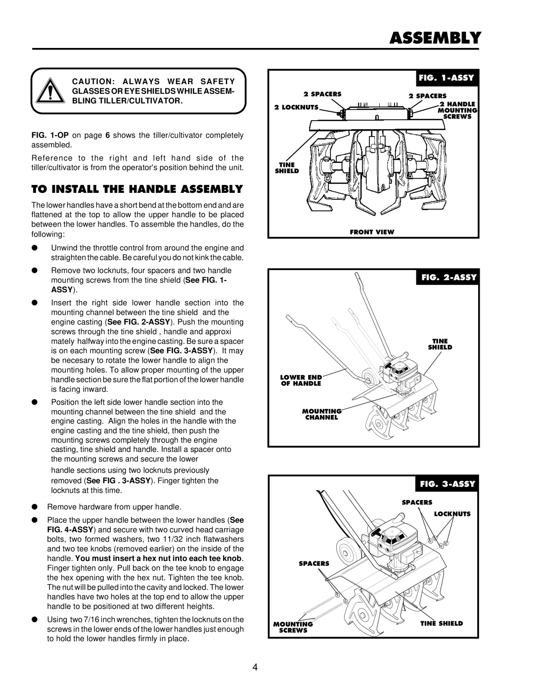
●Remove two locknuts, four spacers and two handle mounting screws from the tine shield (See FIG. 1- ASSY).
●Insert the right side lower handle section into the mounting channel between the tine shield and the engine casting (See FIG.
●Position the left side lower handle section into the mounting channel between the tine shield and the engine casting. Align the holes in the handle with the engine casting and the tine shield, then push the mounting screws completely through the engine casting, tine shield and handle. Install a spacer onto the mounting screws and secure the lower
handle sections using two locknuts previously removed (See FIG .
●Remove hardware from upper handle.
●Place the upper handle between the lower handles (See FIG.
●Using two 7/16 inch wrenches, tighten the locknuts on the screws in the lower ends of the lower handles just enough to hold the lower handles firmly in place.
|
| FIG. |
|
| |
2 SPACERS |
|
|
2 SPACERS | ||
2 LOCKNUTS |
| 2 HANDLE |
| MOUNTING | |
|
| |
|
| SCREWS |
TINE
SHIELD
FRONT VIEW
FIG. |
TINE |
SHIELD |
LOWER END |
OF HANDLE |
MOUNTING |
CHANNEL |
Figure 4 |
| FIG. |
| SPACERS |
| LOCKNUTS |
SPACERS |
|
MOUNTING | TINE SHIELD |
SCREWS |
|
4