ASSEMBLY
TO ATTACH NOSE ROLLER (See Fig. 5)
•Assemble brackets "A" and "B" to the inside of mower mounting brackets as shown. Tighten securely.
NOTE: Be sure bracket tabs are positioned in tab holes in mower brackets.
•Position nose roller between brackets and install rod and retainer spring.
• Remove plastic tie strap from mower belt and check |
belt for proper routing in all mower pulley grooves. |
• Slide mower under tractor until it is centered under trac- |
tor.DO NOT connect any pins.When properly centered |
the front mower brackets should be aligned so when |
the front suspension plate is lowered it should slide |
between the mower brackets. |
• Lower attachment lift lever to lowest position. |
• Cut plastic tie and lower front suspension plate. |
LOCK
HEX BOLT
• ATTACH FRONT PLATE - From right side of mower, |
NUTROD
TAB | "B" | |
BRACKET | ||
HOLE | ||
|
"A"
BRACKET
02612
NOSE ROLLER
RETAINER SPRING
position front plate assembly between front mower |
brackets, align holes, position flanged pin notch hori- |
zontally and insert the pin all the way. The notch is in |
line with the hole in pin. |
• Secure pin with double loop retainer spring between |
the plate and mower bracket.If necessary, move mower |
bracket. |
• Go to right hand side of mower and insert pin and |
retainer spring in the same manner. |
FIG. 5
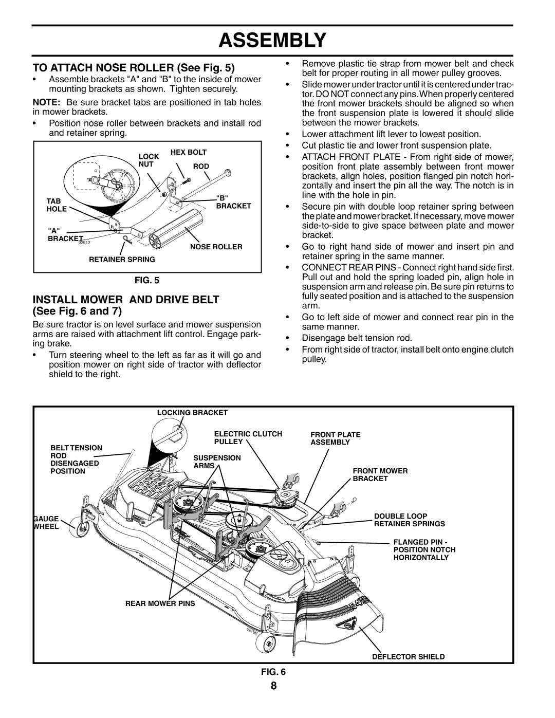
INSTALL MOWER AND DRIVE BELT (See Fig. 6 and 7)
Be sure tractor is on level surface and mower suspension arms are raised with attachment lift control. Engage park- ing brake.
•Turn steering wheel to the left as far as it will go and position mower on right side of tractor with deflector shield to the right.
•CONNECT REAR PINS - Connect right hand side first. Pull out and hold the spring loaded pin, align hole in suspension arm and release pin. Be sure pin returns to fully seated position and is attached to the suspension arm.
•Go to left side of mower and connect rear pin in the same manner.
•Disengage belt tension rod.
•From right side of tractor, install belt onto engine clutch pulley.
| LOCKING BRACKET |
| |
| ELECTRIC CLUTCH | FRONT PLATE | |
BELT TENSION | PULLEY | ASSEMBLY | |
|
| ||
ROD | SUSPENSION |
| |
DISENGAGED |
| ||
ARMS | FRONT MOWER | ||
POSITION | |||
| |||
|
| BRACKET | |
GAUGE |
| DOUBLE LOOP | |
| RETAINER SPRINGS | ||
WHEEL |
| ||
|
| ||
|
| FLANGED PIN - | |
|
| POSITION NOTCH | |
|
| HORIZONTALLY | |
| REAR MOWER PINS |
| |
|
| DEFLECTOR SHIELD |
FIG. 6
8