ASSEMBLY
•Remove the two (2) bolts and flat washers securing the seat to cardboard packing. Keep the two (2) bolts only and place them with the two (2) identical bolts and four (4) washers in the parts bag. Discard the flat washers and cardboard packing.
•Release L.H. seat slide on seat pan by pulling out on adjustment handle and sliding it to the rear position exposing seat mounting holes from bottom. Slide R.H. slide to same rear position.
•Mount rear of seat on slides using mounting bolts and lock washers as shown.
•Pull out on adjustment handle and slide seat all the way forward. Install front mounting bolts and lock washers. Tighten all mounting bolts securely.
•Lower seat into operating position and sit on seat.Press clutch/brake pedal all the way down. If operating posi- tion is not comfortable, adjust seat.
•To adjust seat: Grasp adjustment handle and pull out, slide seat to desired position and release adjustment handle.
L.H. SEAT |
|
SLIDE | SEAT |
|
ADJUSTMENT
HANDLE SEAT
PAN
LOCK
WASHERS
02521
R.H. SEAT SLIDE
MOUNTING BOLTS
FIG. 3
NOTE: You may now roll or drive your tractor off the skid. Follow the appropriate instruction below to remove the tractor from the skid.
TO ROLL TRACTOR OFF SKID (See Op- eration section for location and function of controls)
•Press lift lever plunger and raise attachment lift lever to its highest position.
•Release parking brake by depressing brake pedal.
•Place freewheel control in "transmission disengaged position" (See “TO TRANSPORT” in the Operation section of this manual).
•Roll tractor forward off skid.
TO DRIVE TRACTOR OFF SKID (See Op- eration section for location and function of controls)
![]() WARNING: Before starting, read, understand and follow all instructions in the Operation section of this manual. Be sure tractor is in a
WARNING: Before starting, read, understand and follow all instructions in the Operation section of this manual. Be sure tractor is in a
• Be sure all the above assembly steps have been com- pleted.
• Check engine oil level and fill fuel tank with gasoline.
• Place freewheel control in "transmission engaged" position (see "TO TRANSPORT" in Operation section of this manual).
7
•Sit on seat in operating position, depress brake pedal and set the parking brake.
•Press lift lever plunger and raise attachment lift lever to its highest position.
•Start the engine.After engine has started, move throttle control to idle position.
•Release parking brake.
•Slowly move the motion control lever forward and slowly drive tractor off skid.
•Apply brake to stop tractor, set parking brake and place motion control lever in neutral position.
•Turn ignition key to "STOP" position.
Continue with the instructions that follow.
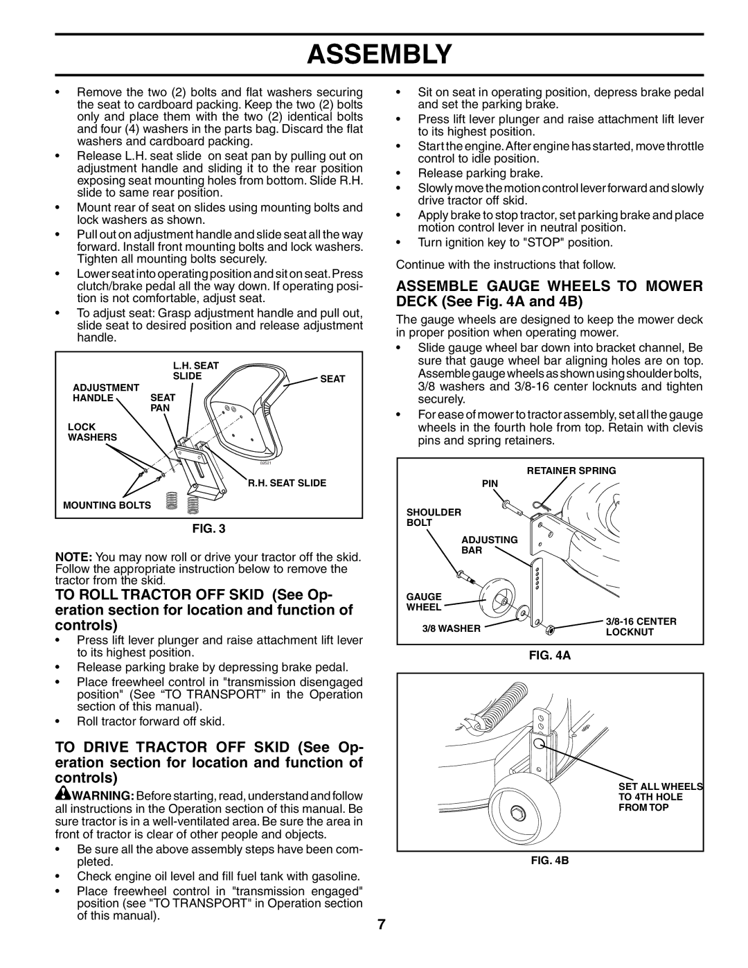
ASSEMBLE GAUGE WHEELS TO MOWER DECK (See Fig. 4A and 4B)
The gauge wheels are designed to keep the mower deck in proper position when operating mower.
•Slide gauge wheel bar down into bracket channel, Be sure that gauge wheel bar aligning holes are on top. Assemble gauge wheels as shown using shoulder bolts, 3/8 washers and
•For ease of mower to tractor assembly, set all the gauge wheels in the fourth hole from top. Retain with clevis pins and spring retainers.
RETAINER SPRING
PIN
SHOULDER
BOLT
ADJUSTING
BAR
GAUGE
WHEEL
3/8 WASHER | ||
LOCKNUT | ||
|
FIG. 4A
SET ALL WHEELS
TO 4TH HOLE
FROM TOP
FIG. 4B