The size of the Air Cap is determined by the size of the center hole. Every Air Cap is stamped with number 1, 2, or 3 to indicate the range in size. The larger the center hole (No. 3), the greater the amount of atomizing air around the Fluid Tip. To ensure proper performance, ensure that the Air Cap hole is large enough to allow atomizing air to flow freely around the Air Cap, but not so large that it will create a distorted pattern. Trial and error is often the best way to select the appropriate Air Cap.
IMPORTANT: Needles and Fluid Tips are sized together – when changing the Needle, the Fluid Tip must be changed as well. Air Caps are sized separately and can be changed without necessarily changing the Needle and Fluid Tip.
Selecting The Proper Needle, Fluid Tip, And Air Cap Combination
To select the proper Needle and Fluid Tip, start with the Needle And Fluid Tip Selection Chart later in this section. Needles and Fluid Tips range in size and should be selected based on the viscosity of the coating being applied and the finish and application speed required. For
To select the proper Air Cap, consider the size of the Needle and Fluid Tip, and finish required. The size of the Air Cap is determined by the size of its center hole. In order for the air to atomize the coating, the hole in the center of the Air Cap must be large enough to allow air to flow freely around the Fluid Tip. Depending on the size of the Fluid Tip, you may have a choice of Air Caps: using a larger size Air Cap may eliminate more overspray (mist), however using a smaller size Air Cap may produce a finer finish.
For information about testing your Needle/Fluid Tip/Air Cap combination, refer to Section 3.8 of this manual – Testing Prior To Spraying.
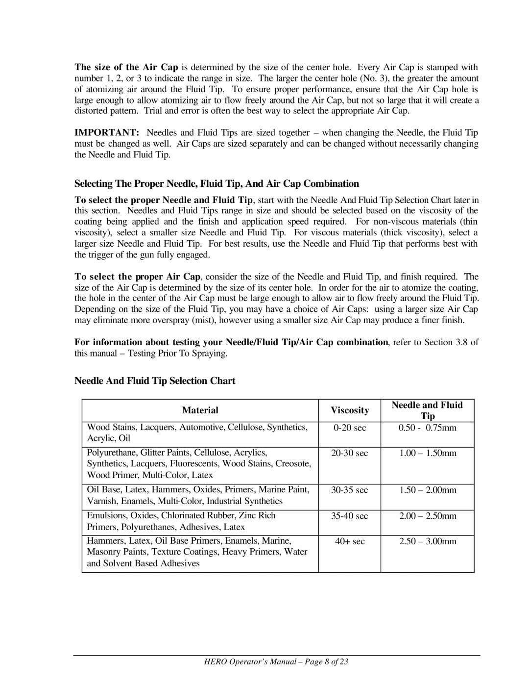
Needle And Fluid Tip Selection Chart
Material | Viscosity | Needle and Fluid | |
Tip | |||
|
| ||
Wood Stains, Lacquers, Automotive, Cellulose, Synthetics, | 0.50 - 0.75mm | ||
Acrylic, Oil |
|
| |
|
|
| |
Polyurethane, Glitter Paints, Cellulose, Acrylics, | 1.00 – 1.50mm | ||
Synthetics, Lacquers, Fluorescents, Wood Stains, Creosote, |
|
| |
Wood Primer, |
|
| |
|
|
| |
Oil Base, Latex, Hammers, Oxides, Primers, Marine Paint, | 1.50 – 2.00mm | ||
Varnish, Enamels, |
|
| |
|
|
| |
Emulsions, Oxides, Chlorinated Rubber, Zinc Rich | 2.00 – 2.50mm | ||
Primers, Polyurethanes, Adhesives, Latex |
|
| |
|
|
| |
Hammers, Latex, Oil Base Primers, Enamels, Marine, | 40+ sec | 2.50 – 3.00mm | |
Masonry Paints, Texture Coatings, Heavy Primers, Water |
|
| |
and Solvent Based Adhesives |
|
| |
|
|
|
HERO Operator’s Manual – Page 8 of 23