4. LED Indicators & Terminal Resistance
The table below shows the meanings of LED indicators on the
POWER LED
(Red Light)
on | module | |
active | ||
| ||
|
| |
off | module | |
inactive | ||
| ||
|
|
TD LED
(Green Light)
messages
flashing
transmitting
no message
off
transmitting
RD LED
(Green Light)
messages
flashing
receiving
no message
off
receiving
The switch at bottom of
Active Inactive
(Enable) (Disable)
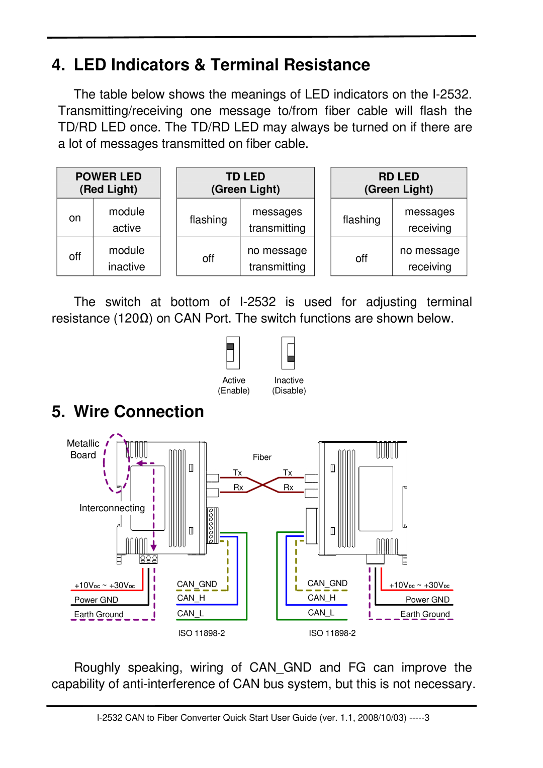
5. Wire Connection
Metallic
Board
Interconnecting
Fiber
TxTx
Rx ![]() Rx
Rx
+10VDC ~ +30VDC
Power GND
Earth Ground
CAN_GND |
CAN_H |
CAN_L |
ISO |
CAN_GND |
CAN_H |
CAN_L |
ISO |
+10VDC ~ +30VDC
Power GND
Earth Ground
Roughly speaking, wiring of CAN_GND and FG can improve the capability of
3 |
