IMAGE REVERSING CIRCUIT__________________________________________________
The image r eversing cir cuit is m ounted inside the housing. The circuit reverses (flips) t he image and words on the LCD s creen so that when the i mage is reflec ted in the exte rnal mirror, it app ears cor rect left-
Secure the camera to t he tray and partially slide the camera and tray inside the housing so y ou can th en connect the cable from the reversing circ uit to the blue LANC port on th e camera. The reversing circuit will automatically turn ON when connected to the camera and the camera is ON; t he image and wo rds in the LCD screen will a ppear in reverse.
On/Off Switch
An on/off switch is featured on the reversing cir cuit. Use the re versing circuit control on the housing t o access th e on/off switch on th e circuit. The circuit wi ll automatically turn ON w hen connected to the camera an d the camera is ON.
When tur ning t he camera OFF, there is a 5- minute standby power down d elay on the camera that occur s when the reversing circuit is ON d uring power down. Therefore to a void the
Functions Locked Out
When the reversing cir cuit is ON, some camera functions may be locked out. To correct for such a pr oblem, temporarily turn the circu it OFF, change the funct ion on the camera, and then turn the circuit back ON.
FINAL PREPARATION_________________________________________________________
Remove the lens cap and cord from the came ra. Otherwise, they may interfere with the hou sing seal.
The camera's auto focus featur e is utilized unde rwater. For be st results, move in close to your s ubject and use the wide angle range to sh oot thr u as l ittle water as possible. The full zoom range is accessible underwater .
Turn the camera’s
WHITE BALANCE_____________________________________________________________
Initially set the white balance to Auto. Use the touch scre en controls on the housing to change white balance .
Color Filter: When using the color filter (during the day), se t camera white balance to Indoor for 0
IN S T A L L A T IO N
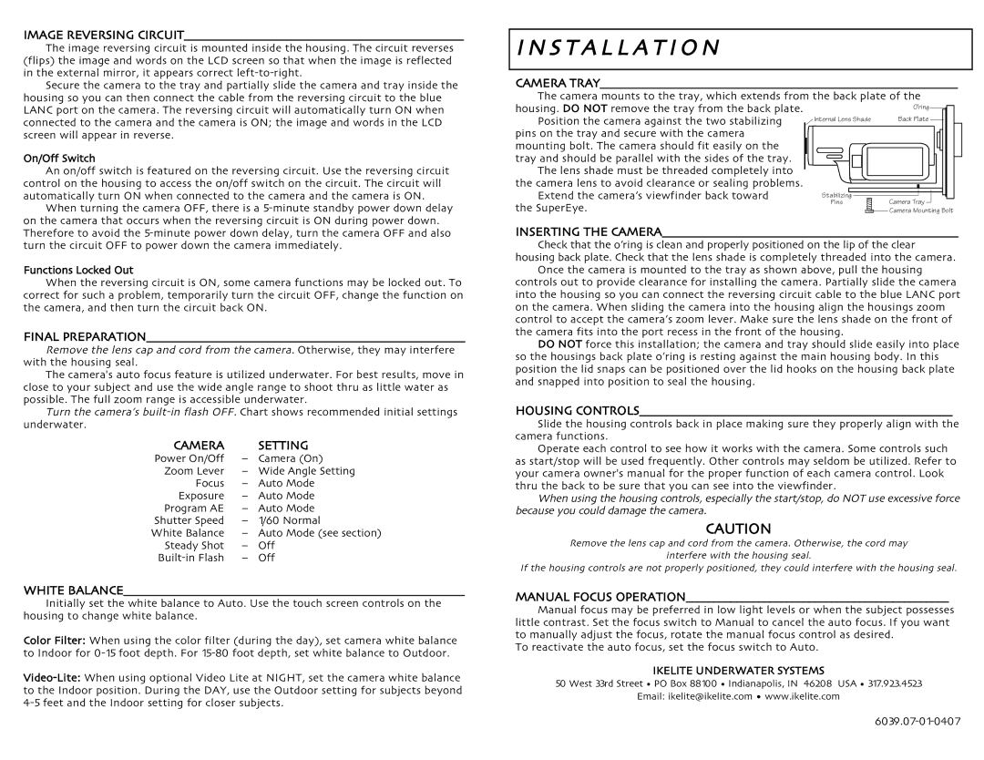
CAMERA TRAY________________________________________________________________
The camera mounts to the tray, which extends from the back plate of the housing. DO NOT remove the tray from the back plate.
Position the camera against the two stabilizing
pins on the tray and secure with the camera mounting bolt. The camera should fit easily on the
tray and should be parallel with the sides of th e tray. The lens shade must be threaded completely into
the camera lens to avoid clearance or sealing problems. Extend the camera’s viewfinder back toward
the SuperEye.![]()
![]() INSERTING THE CAMERA_____________________________________________________
INSERTING THE CAMERA_____________________________________________________
Check that the o’ring is clean and properly positioned on the lip of the clear housing back plate. Check that the lens shade is completely threaded into the c amera.
Once the camera is mounted to the tray as sh own above, pull the housing controls out to provide clearance for installing the camera. Partially slide the camera into the housing so you can connect the reversing circuit cable to the blue LANC port on the camera. When sliding the camera into the housing align the housings zoom control to accept the camera’s zoom lever. Make sure the lens shade on the front of the camera fits into the port recess in the front of the housing.
DO NOT force this installation; the camera and tray should slide easily in to place so the housings back plate o’ring is resting against the main housing body. In this position the lid snaps can be positioned over the lid hooks on the h ousing back plate and snapped into position to seal the housing.
HOUSING CONTROLS________________________________________________________
Slide the housing controls back in place making sure they properly align with the camera functions.
Operate each control to see how it works with the camera. Some controls such as start/stop will be used frequently. Other controls may seldom be utilized. Refer to your camera owner's manual for the proper function of each camera control. Look thru the back to be sure that you can see into the viewfinder.
When using the housing controls, especially the start/stop,do NOT use excessive force because you could damage the camera.CAUTION
Remove the lens cap and c ord from the cam era. Otherwise, the cord may interfere with the housing seal.
If the housing controls are not properly positioned, they could interfere with the housing seal.
MANUAL FOCUS OPERATION_______________________________________________
Manual focus may be preferred in low lig ht levels or w hen the subject possesses little contrast. Set the focus switch to Manual to cancel the a uto focus. If yo u want to manually adjust the focus, rotate the manual focus control as d esired.
To reactivate the auto focus, set the focus switch to Auto.
IKELITE UNDERWATER SYSTEMS
50 West 33rd Street • PO Box 88100 • Indianapolis, IN 46208 USA • 317.923.4523 Email: ikelite@ikelite.com • www.ikelite.com