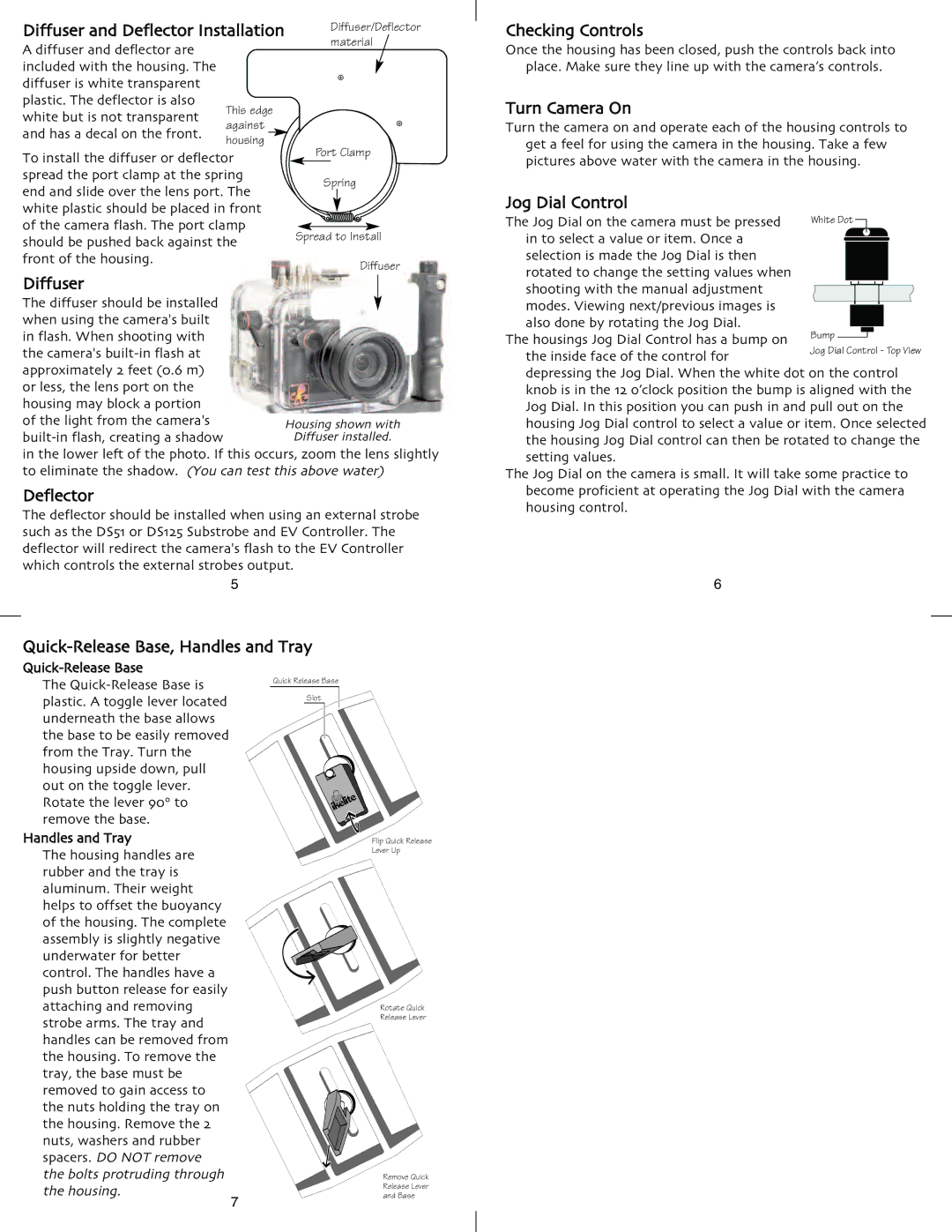
Diffuser and Deflector Installation |
|
|
| Diffuser/Deflector | |||||||
|
|
| material | ||||||||
A diffuser and deflector are |
|
|
|
|
|
|
|
|
|
|
|
included with the housing. The |
|
|
|
|
|
|
|
|
|
|
|
diffuser is white transparent |
|
|
|
|
|
|
|
|
|
|
|
plastic. The deflector is also | This edge |
|
|
|
|
|
|
|
|
|
|
white but is not transparent | against |
|
|
|
|
|
|
|
|
|
|
and has a decal on the front. | housing |
|
|
|
|
|
|
|
|
|
|
To install the diffuser or deflector |
|
| Port Clamp | ||||||||
|
|
|
|
|
|
|
|
|
| ||
spread the port clamp at the spring |
|
| Spring | ||||||||
end and slide over the lens port. The |
|
|
|
|
|
|
|
|
|
| |
|
|
|
|
|
|
|
|
|
| ||
white plastic should be placed in front |
|
|
|
|
|
|
|
|
|
| |
of the camera flash. The port clamp |
|
|
|
|
|
|
|
|
|
| |
|
|
|
|
|
|
|
|
|
| ||
|
|
|
|
|
|
|
|
|
| ||
should be pushed back against the | Spread to Install | ||||||||||
front of the housing. |
|
|
|
|
|
|
|
| Diffuser | ||
Diffuser |
|
|
|
|
|
|
|
|
|
|
|
|
|
|
|
|
|
|
|
|
|
| |
The diffuser should be installed |
|
|
|
|
|
|
|
|
|
|
|
|
|
|
|
|
|
|
|
|
|
| |
when using the camera's built |
|
|
|
|
|
|
|
|
|
|
|
in flash. When shooting with |
|
|
|
|
|
|
|
|
|
|
|
the camera's |
|
|
|
|
|
|
|
|
|
|
|
approximately 2 feet (0.6 m) |
|
|
|
|
|
|
|
|
|
|
|
or less, the lens port on the |
|
|
|
|
|
|
|
|
|
|
|
housing may block a portion |
| Housing shown with | |||||||||
of the light from the camera's |
| ||||||||||
| Diffuser installed. | ||||||||||
in the lower left of the photo. If this occurs, zoom the lens slightly to eliminate the shadow. (You can test this above water)
Deflector
The deflector should be installed when using an external strobe such as the DS51 or DS125 Substrobe and EV Controller. The deflector will redirect the camera's flash to the EV Controller which controls the external strobes output.
5
Checking Controls
Once the housing has been closed, push the controls back into place. Make sure they line up with the camera’s controls.
Turn Camera On
Turn the camera on and operate each of the housing controls to
get a feel for using the camera in the housing. Take a few pictures above water with the camera in the housing.
Jog Dial Control |
|
|
|
|
|
|
|
|
|
The Jog Dial on the camera must be pressed | White Dot |
|
| ||||||
|
|
|
| ||||||
in to select a value or item. Once a |
|
|
|
|
|
|
|
|
|
|
|
|
|
|
|
|
|
| |
selection is made the Jog Dial is then |
|
|
|
|
|
|
|
|
|
rotated to change the setting values when |
|
|
|
|
|
|
|
|
|
shooting with the manual adjustment |
|
|
|
|
|
|
|
|
|
|
|
|
|
|
|
|
|
| |
modes. Viewing next/previous images is |
|
|
|
|
|
|
|
|
|
|
|
|
|
|
|
|
|
| |
|
|
|
|
|
|
|
|
| |
also done by rotating the Jog Dial. | Bump |
|
|
|
|
|
|
|
|
|
|
|
|
|
|
| |||
| |||||||||
The housings Jog Dial Control has a bump on | Jog Dial Control - Top View | ||||||||
the inside face of the control for |
|
|
|
|
|
|
|
|
|
depressing the Jog Dial. When the white dot on the control knob is in the 12 o’clock position the bump is aligned with the Jog Dial. In this position you can push in and pull out on the housing Jog Dial control to select a value or item. Once selected the housing Jog Dial control can then be rotated to change the setting values.
The Jog Dial on the camera is small. It will take some practice to become proficient at operating the Jog Dial with the camera housing control.
6
Quick-Release Base, Handles and Tray
Quick-Release Base
The
out on the toggle lever. Rotate the lever 90° to
remove the base.
Handles and Tray
The housing handles are rubber and the tray is aluminum. Their weight helps to offset the buoyancy of the housing. The complete assembly is slightly negative underwater for better control. The handles have a push button release for easily attaching and removing strobe arms. The tray and handles can be removed from the housing. To remove the tray, the base must be removed to gain access to the nuts holding the tray on the housing. Remove the 2 nuts, washers and rubber spacers. DO NOT remove
the bolts protruding through the housing.
7
Flip Quick Release Lever Up
Rotate Quick Release Lever
Remove Quick
Release Lever
and Base