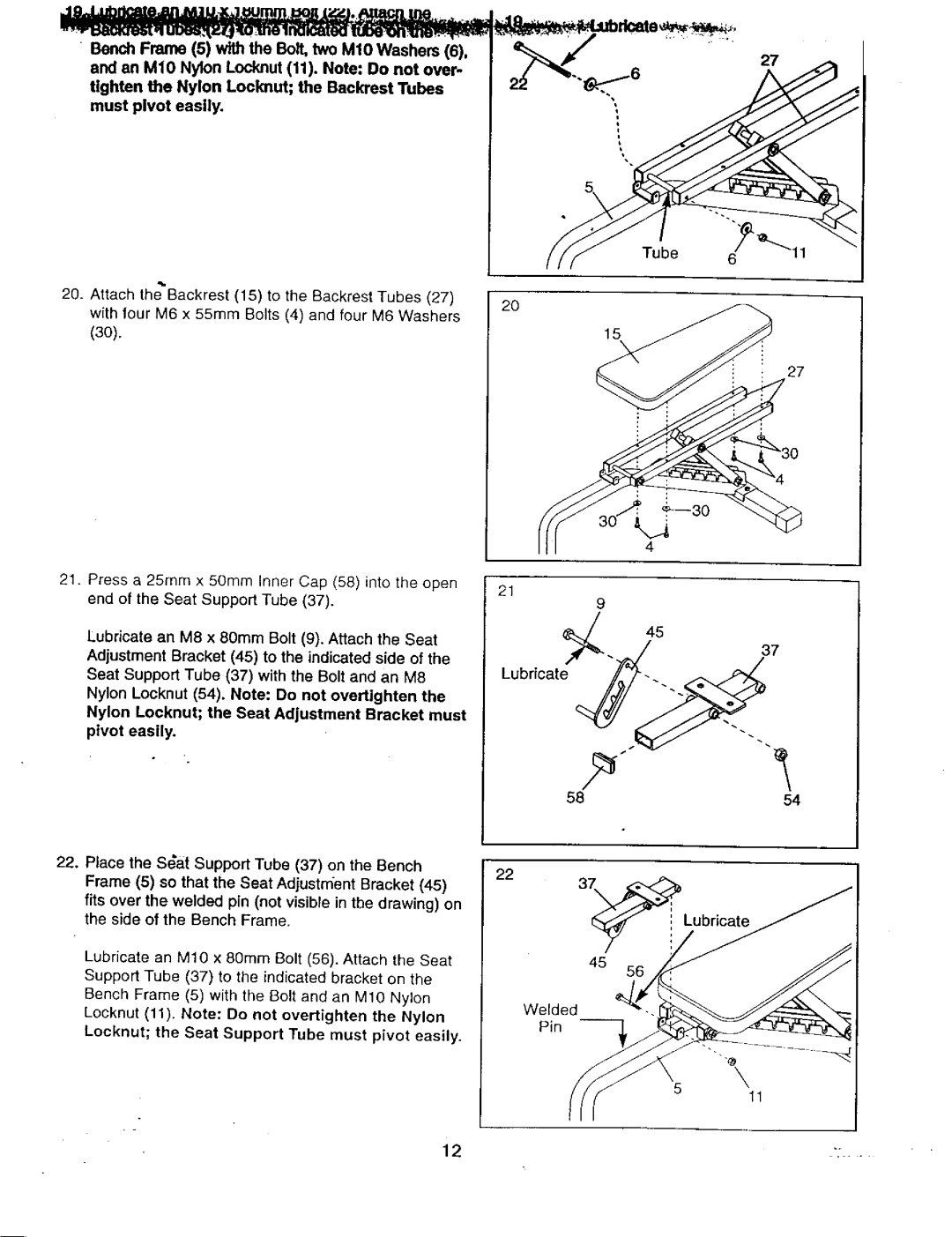
and an M10 Nylon Locknut (11). Note: Do not over- tighten the Nylon Locknut; the Backrest Tubes must pivot easily.
20.Attach theBackrest (15) to the Backrest Tubes (27) with tour M6 x 55ram Bolts (4) and four M8 Washers (3O).
21.Press a 25ram x 5Ornm inner Cap (58) into the open end of the Seat Support Tube (37).
Lubricate an M8 x 80mm Bolt (9). Attach the Seat Adjustment Bracket (45) to the indicated side of the Seat Support Tube (37) with the Bolt and an M8 Nylon Locknut (54). Note: Do not overtighten the
Nylon Leeknut; the Seat Adjustment Bracket must pivot easily.
27
Tube 6
2O
15
: 27
21
9
45
37
Lubricate
| 58 | 54 |
22. Place the S_a_tSupport Tube (37) on the Bench | 22 |
|
Frame (5) so that the Seat Adjustrrfent Bracket (45) |
| |
|
| |
fits over the welded pin (not visible in tbe drawing) on |
|
|
the side of the Bench Frame. | 37_ | Lubricate |
| ||
Lubricate an M10 x 80mm Bolt (56). Attach the Seat | 45 | 56 |
|
|
Support Tube (37) to the indicated bracket on the |
| |
Bench Frame (5) with the Belt and an M10 Nylon | Welded | |
Locknut (11)+ Note: Do not overtighten the Nylon | ||
Pin | ||
Locknut; the Seat Support Tube must pivot easily• | ||
| ||
| ||
| 11 |
12 | ": • - |
