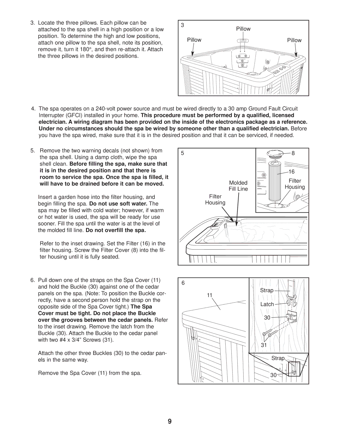
3.Locate the three pillows. Each pillow can be attached to the spa shell in a high position or a low position. To determine the high and low positions, attach one pillow to the spa shell, note its position, remove it, turn it 180°, and then
3 | Pillow |
| |
Pillow | Pillow |
4.The spa operates on a
5.Remove the two warning decals (not shown) from the spa shell. Using a damp cloth, wipe the spa shell clean. Before filling the spa, make sure that it is in the desired position and that there is room to service the spa. Once the spa is filled, it will have to be drained before it can be moved.
Insert a garden hose into the filter housing, and begin filling the spa. Do not use soft water. The spa may be filled with cold water; however, if warm or hot water is used, the spa will be ready for use sooner. Fill the spa until the water is at the level of the molded fill line. Do not overfill the spa.
Refer to the inset drawing. Set the Filter (16) in the filter housing. Screw the Filter Cover (8) into the fil- ter housing until it is fully seated.
6.Pull down one of the straps on the Spa Cover (11) and hold the Buckle (30) against one of the cedar panels on the spa. (Note: To position the Buckle cor- rectly, have a second person hold the strap on the opposite side of the Spa Cover tight.) The Spa
Cover must be tight. Do not place the Buckle over the grooves between the cedar panels. Refer to the inset drawing. Remove the latch from the Buckle (30). Attach the Buckle to the cedar panel with two #4 x 3/4” Screws (31).
Attach the other three Buckles (30) to the cedar pan- els in the same way.
Remove the Spa Cover (11) from the spa.
5 |
| 8 |
|
| 16 |
| Molded | Filter |
| Housing | |
| Fill Line | |
|
| |
| Filter |
|
| Housing |
|
6 |
|
|
| 11 | Strap |
|
| |
|
| Latch |
|
| 30 |
|
| 31 |
|
| Strap |
|
| 30 |
9