Enabling TX and FX LinkLoss
In order to enable the LinkLoss features, remove the cover from the unit and place the jumpers accordingly. Follow the instructions below, referencing the diagram.
1.Make sure that there is no power going to the unit by UNPLUGGING THE POWER CORD.
2.Using a Philllips screwdriver, remove the screws on the corners of the cover.
3.Remove the cover and find the
4.Replace the cover and tighten the screw to secure the cover.
Refer to the following diagrams and table for jumper location and settings.
Using FiberAlert and LinkLoss
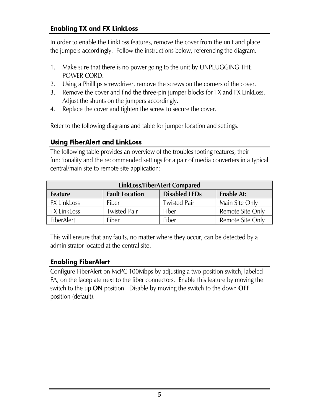
The following table provides an overview of the troubleshooting features, their functionality and the recommended settings for a pair of media converters in a typical central/main site to remote site application:
LinkLoss/FiberALert Compared
Feature | Fault Location | Disabled LEDs | Enable At: |
FX LinkLoss | Fiber | Twisted Pair | Main Site Only |
TX LinkLoss | Twisted Pair | Fiber | Remote Site Only |
FiberAlert | Fiber | Fiber | Remote Site Only |
This will ensure that any faults, no matter where they occur, can be detected by a administrator located at the central site.
Enabling FiberAlert
Configure FiberAlert on McPC 100Mbps by adjusting a
5
