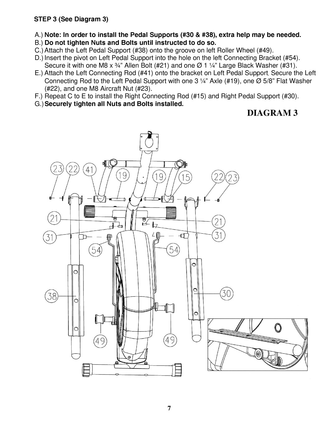
STEP 3 (See Diagram 3)
A.) Note: In order to install the Pedal Supports (#30 & #38), extra help may be needed. B.) Do not tighten Nuts and Bolts until instructed to do so.
C.) Attach the Left Pedal Support (#38) onto the groove on left Roller Wheel (#49).
D.) Insert the pivot on Left Pedal Support into the hole on the left Connecting Bracket (#54). Secure it with one M8 x ¾” Allen Bolt (#21) and one Ø 1 ¼” Large Black Washer (#31).
E.) Attach the Left Connecting Rod (#41) onto the bracket on Left Pedal Support. Secure the Left Connecting Rod to the Left Pedal Support with one 3 ¼” Axle (#19), one Ø 5/8” Flat Washer (#22), and one M8 Aircraft Nut (#23).
F.) Repeat C to E to install the Right Connecting Rod (#15) and Right Pedal Support (#30). G.)Securely tighten all Nuts and Bolts installed.
DIAGRAM 3
7