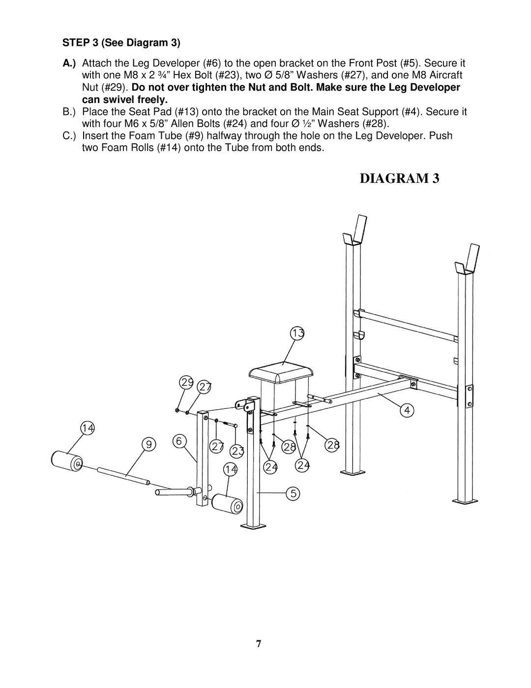
STEP 3 (See Diagram 3)
A.) Attach the Leg Developer (#6) to the open bracket on the Front Post (#5). Secure it with one M8 x 2 ¾” Hex Bolt (#23), two Ø 5/8” Washers (#27), and one M8 Aircraft Nut (#29). Do not over tighten the Nut and Bolt. Make sure the Leg Developer can swivel freely.
B.) Place the Seat Pad (#13) onto the bracket on the Main Seat Support (#4). Secure it with four M6 x 5/8” Allen Bolts (#24) and four Ø ½” Washers (#28).
C.) Insert the Foam Tube (#9) halfway through the hole on the Leg Developer. Push two Foam Rolls (#14) onto the Tube from both ends.
DIAGRAM 3
7