ASSEMBLY INSTRUCTION
Tools Required Assembling the Machine: Two Adjustable Wrenches and Allen Wrenches
NOTE: It is strongly recommended two or more people to assemble this machine to avoid possible injury.
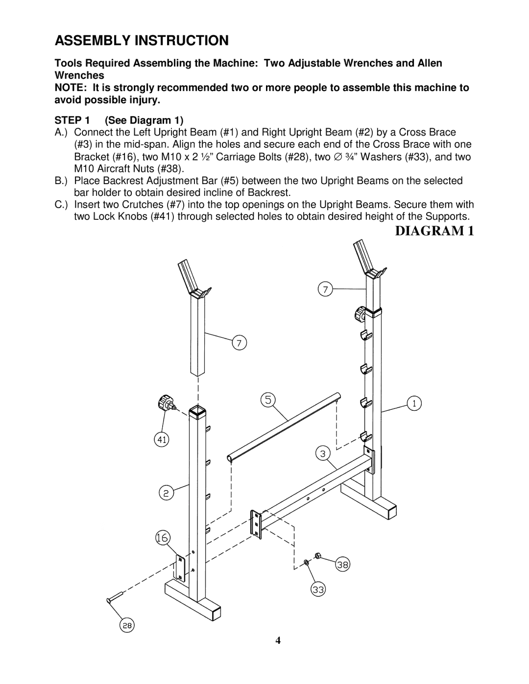
STEP 1 (See Diagram 1)
A.) Connect the Left Upright Beam (#1) and Right Upright Beam (#2) by a Cross Brace (#3) in the
B.) Place Backrest Adjustment Bar (#5) between the two Upright Beams on the selected bar holder to obtain desired incline of Backrest.
C.) Insert two Crutches (#7) into the top openings on the Upright Beams. Secure them with two Lock Knobs (#41) through selected holes to obtain desired height of the Supports.
DIAGRAM 1
4