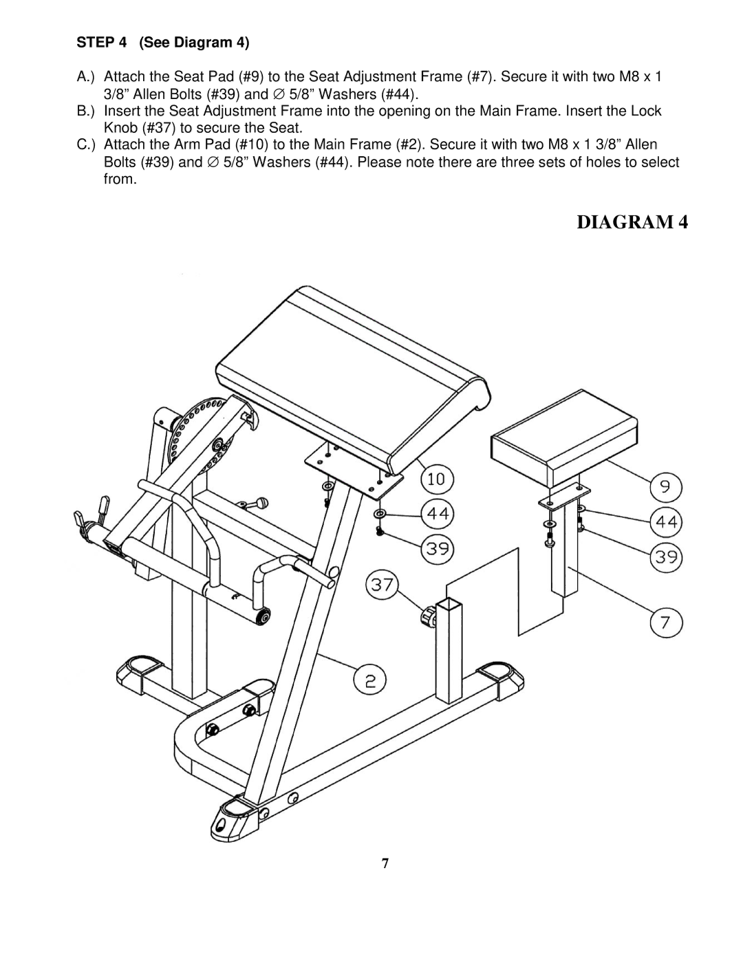
STEP 4 (See Diagram 4)
A.) Attach the Seat Pad (#9) to the Seat Adjustment Frame (#7). Secure it with two M8 x 1 3/8” Allen Bolts (#39) and ∅ 5/8” Washers (#44).
B.) Insert the Seat Adjustment Frame into the opening on the Main Frame. Insert the Lock Knob (#37) to secure the Seat.
C.) Attach the Arm Pad (#10) to the Main Frame (#2). Secure it with two M8 x 1 3/8” Allen Bolts (#39) and ∅ 5/8” Washers (#44). Please note there are three sets of holes to select from.
DIAGRAM 4
7