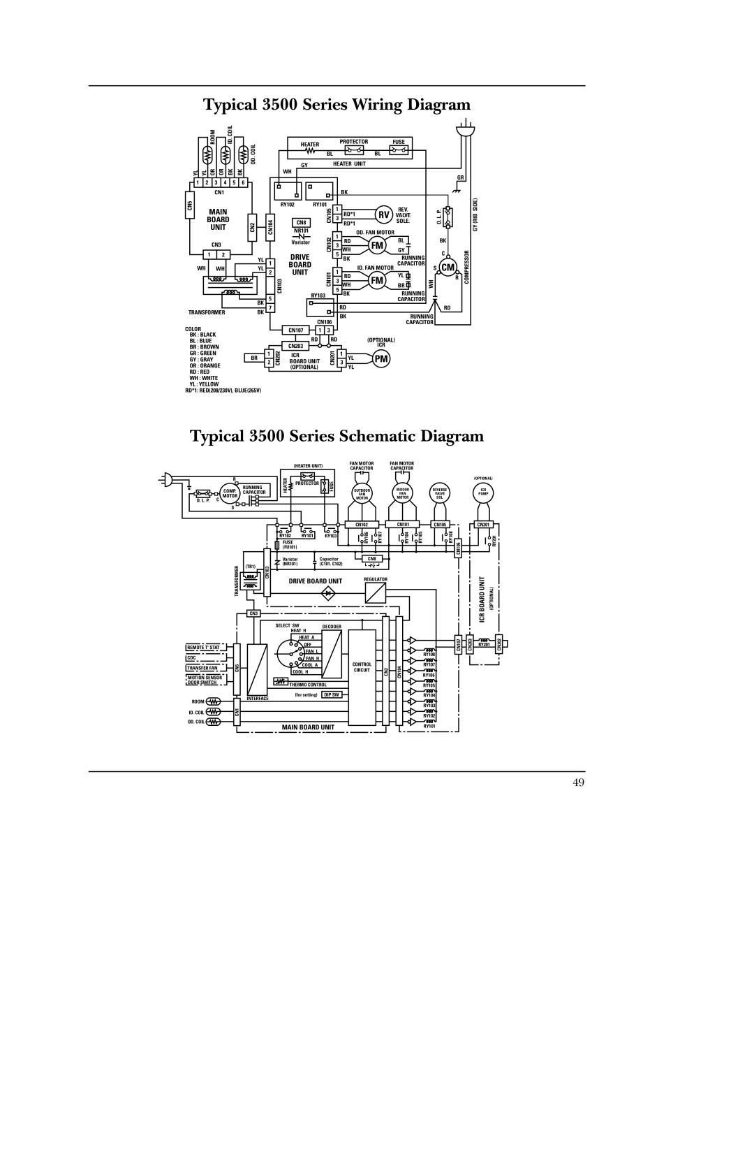
Typical 3500 Series Wiring Diagram


ROOM


ID. COIL

COIL


OD.

YL

YL

OR


OR

BK

BK

1

2

3

4

5

6


CN1


CN5


MAIN


BOARD

CN2


UNIT


CN3


1


2


YL


WH


WH


YL

BK

TRANSFORMERBK

COLOR

BK : BLACK

BL : BLUE

BR : BROWN

GR : GREEN

GY : GRAYBR

OR : ORANGE

RD : RED

WH : WHITE

YL : YELLOW

RD*1: RED(208/230V), BLUE(265V)


HEATER


PROTECTOR

FUSE


BL


BL


GY


HEATER UNIT


WH


GR


CN104


CN105


BK


O.L. P.


(RIBGY SIDE)


NR101


OD. FAN MOTOR


RY102

RY101

1


REV.


3

RD*1

RV

VALVE


CN8


RD*1


SOLE.


Varistor

RY103CN101CN102

1

RD

FM

BL


BK


3


WH

GY


C


COMPRESSOR


CN103


5


WH


BK


RUNNING


DRIVE


5

BK


RUNNING


1


BOARD


CAPACITOR


S

CM


2


UNIT


1

RD

FM

YL


R


3


WH

BR


5


CAPACITOR


7


RD


RD


CN106


BK


RUNNING


CAPACITOR


CN107

1

3


RD

RD


(OPTIONAL)


2

CN202

CN203


CN201

3 YL

ICR


BOARD UNIT

PM


1


ICR


1


(OPTIONAL)


YL


Typical 3500 Series Schematic Diagram

R

RUNNING

COMP. CAPACITOR

MOTOR

O. L . P. C

S

HEATER

(HEATER UNIT)

PROTECTOR

FUSE


FAN MOTOR

FAN MOTOR


CAPACITOR

CAPACITOR


(OPTIONAL)

OUTDOOR

INDOOR

REVERSE

ICR

FAN

FAN

VALVE

PUMP

MOTOR

MOTOR

SOL.


TRANSFORMER

(TR1)

CN103

RY102 RY101 RY103

FUSE (FU101)

Varistor

Capacitor

(NR101)

(C101. C102)

DRIVE BOARD UNIT

CN102

RY106

RY107


CN8

REGULATOR

CN101

RY104

RY105

CN105

RY108

CN106

CN201


RY201

BOARD UNIT

(OPTIONAL)

CN3


SELECT SW

DECODER

HEAT H


HEAT A


ICR

REMOTE T' STAT

CDC

TRANSFER FAN

MOTION SENSOR DOOR SWITCH

ROOM ID. COIL OD. COIL


OFF


FAN L


FAN H


CN5

COOL A

CONTROL

CN2

COOL H

CIRCUIT


THERMO CONTROL


(for setting)

DIP SW


INTERFACE


CN1


MAIN BOARD UNIT


CN104

RY108

RY107

RY106

RY105

RY104

RY103

RY102

RY101

CN107

CN203

RY201

CN202

49

Page 49
Image 49
GE 5500 manual Typical 3500 Series Wiring Diagram, Typical 3500 Series Schematic Diagram, Board Unit

5500 specifications

The GE 5500 is a sophisticated gas turbine that represents a benchmark in the realm of power generation technology. Known for its impressive performance and efficiency, the GE 5500 has garnered attention in various industries, particularly in energy production. Designed for combined-cycle applications, this turbine effectively leverages both gas and steam cycles to optimize electricity generation.

One of the standout features of the GE 5500 is its advanced aerodynamics, which enhance the efficiency of the combustion process. The turbine employs state-of-the-art combustion technology that allows for high operational flexibility and minimizes emissions, meeting stringent environmental standards. This is particularly important in today’s energy landscape, where sustainability is a crucial focus.

The GE 5500 is equipped with a robust control system that utilizes digital twin technology. This innovative approach allows operators to simulate and analyze the performance of the turbine virtually, leading to improved operational efficiency and reduced downtime. Additionally, this turbine features an integrated health monitoring system that provides real-time data on performance metrics, allowing for predictive maintenance and enhancing overall reliability.

The materials used in the construction of the GE 5500 are engineered to withstand high temperatures and stress levels, ensuring longevity and durability. This includes high-performance alloys that maintain structural integrity even under extreme operating conditions.

Installation and maintenance of the GE 5500 are streamlined through its modular design, which simplifies access to components and reduces service time. This efficiency translates into lower operational costs, making the GE 5500 an economically favorable choice for utilities and independent power producers.

Furthermore, the GE 5500 can be integrated into a variety of power plant configurations, whether for peaking power or baseload operations, which adds to its versatility. Its ability to quickly ramp up production makes it particularly valuable in an energy market characterized by fluctuating demand.

Overall, the GE 5500 gas turbine is a remarkable engineering feat that combines cutting-edge technology with practical design. Its efficiency, reliability, and adaptability position it as a leading choice for power generation needs, meeting the requirements of modern energy systems while contributing to a more sustainable future.