Latent System Capacity

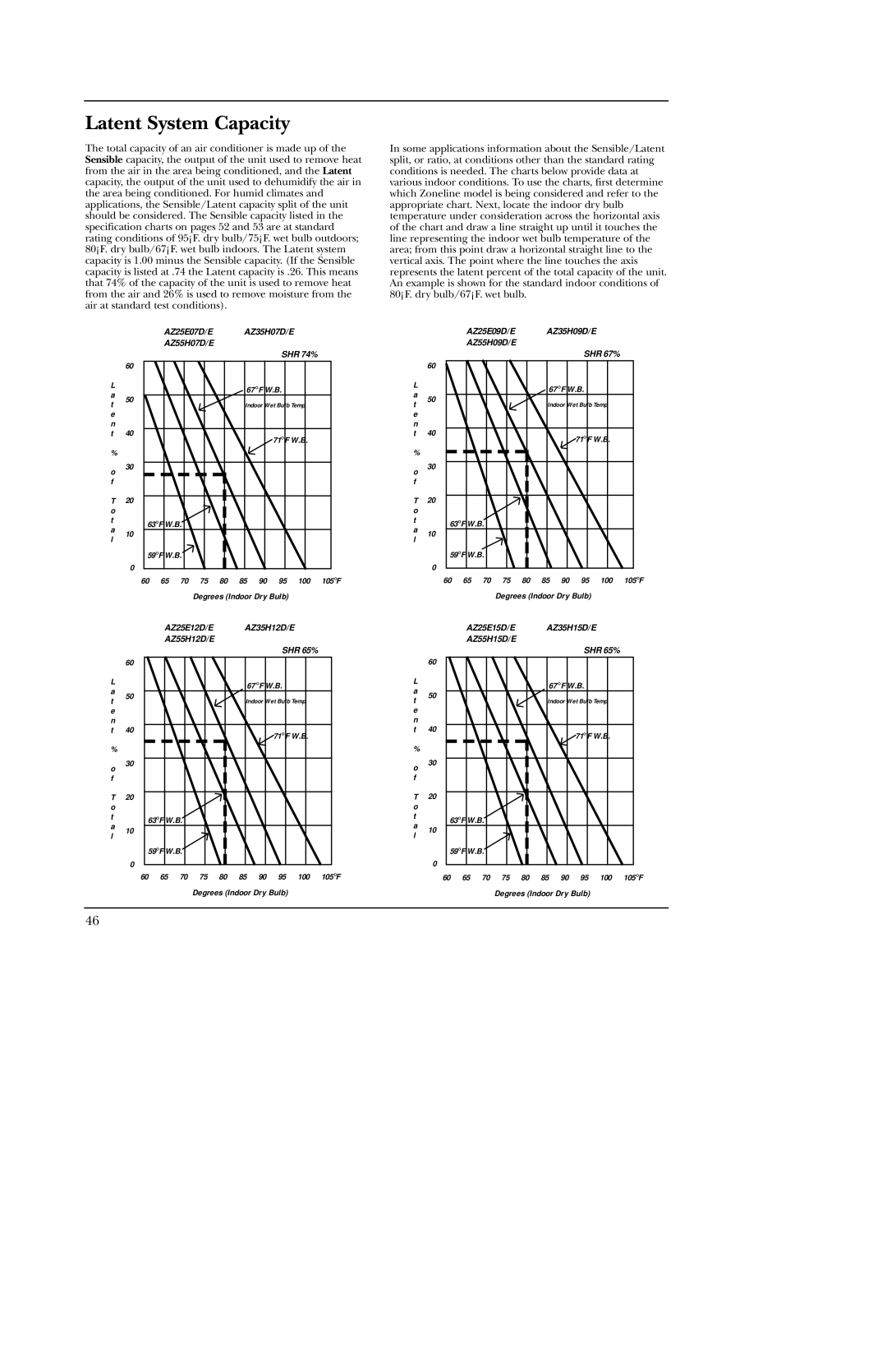
The total capacity of an air conditioner is made up of the Sensible capacity, the output of the unit used to remove heat from the air in the area being conditioned, and the Latent capacity, the output of the unit used to dehumidify the air in the area being conditioned. For humid climates and applications, the Sensible/Latent capacity split of the unit should be considered. The Sensible capacity listed in the specification charts on pages 52 and 53 are at standard rating conditions of 95°F. dry bulb/75°F. wet bulb outdoors; 80°F. dry bulb/67°F. wet bulb indoors. The Latent system capacity is 1.00 minus the Sensible capacity. (If the Sensible capacity is listed at .74 the Latent capacity is .26. This means that 74% of the capacity of the unit is used to remove heat from the air and 26% is used to remove moisture from the air at standard test conditions).

AZ25E07D/E AZ35H07D/E

AZ55H07D/E

SHR 74%


60


L


67 ° F W.B.


a

50


t


Indoor Wet Bulb Temp


e


n

40


t


71° F W.B.


%


o

30


f


T

20


o


t

63°F W.B.


a


10


l


59°F W.B.


0


60

65

70

75

80

85

90

95

100

105°F


Degrees (Indoor Dry Bulb)


AZ25E12D/E AZ35H12D/E

AZ55H12D/E

SHR 65%


60


L


67 °F W.B.


a

50


t


Indoor Wet Bulb Temp


e


n

40


t


71° F W.B.


%


o

30


f


T

20


o


t

63°F W.B.


a


10


l


59°F W.B.


0


60

65

70

75

80

85

90

95

100

105°F


Degrees (Indoor Dry Bulb)


In some applications information about the Sensible/Latent split, or ratio, at conditions other than the standard rating conditions is needed. The charts below provide data at various indoor conditions. To use the charts, first determine which Zoneline model is being considered and refer to the appropriate chart. Next, locate the indoor dry bulb temperature under consideration across the horizontal axis of the chart and draw a line straight up until it touches the line representing the indoor wet bulb temperature of the area; from this point draw a horizontal straight line to the vertical axis. The point where the line touches the axis represents the latent percent of the total capacity of the unit. An example is shown for the standard indoor conditions of 80°F. dry bulb/67°F. wet bulb.

AZ25E09D/E AZ35H09D/E

AZ55H09D/E

SHR 67%


60


L


67 ° F W.B.


a

50


t


Indoor Wet Bulb Temp


e


n

40


t


71° F W.B.


%


o

30


f


T

20


o


t

63°F W.B.


a


10


l


59°F W.B.


0


60

65

70

75

80

85

90

95

100

105°F


Degrees (Indoor Dry Bulb)


AZ25E15D/E AZ35H15D/E

AZ55H15D/E

SHR 65%


60


L


67 ° F W.B.


a

50


t


Indoor Wet Bulb Temp


e


n

40


t


71° F W.B.


%


o

30


f


T

20


o


t

63°F W.B.


a


10


l


59°F W.B.


0


60

65

70

75

80

85

90

95

100

105°F


Degrees (Indoor Dry Bulb)


46

Page 46
Image 46
GE 5500 manual Latent System Capacity

5500 specifications

The GE 5500 is a sophisticated gas turbine that represents a benchmark in the realm of power generation technology. Known for its impressive performance and efficiency, the GE 5500 has garnered attention in various industries, particularly in energy production. Designed for combined-cycle applications, this turbine effectively leverages both gas and steam cycles to optimize electricity generation.

One of the standout features of the GE 5500 is its advanced aerodynamics, which enhance the efficiency of the combustion process. The turbine employs state-of-the-art combustion technology that allows for high operational flexibility and minimizes emissions, meeting stringent environmental standards. This is particularly important in today’s energy landscape, where sustainability is a crucial focus.

The GE 5500 is equipped with a robust control system that utilizes digital twin technology. This innovative approach allows operators to simulate and analyze the performance of the turbine virtually, leading to improved operational efficiency and reduced downtime. Additionally, this turbine features an integrated health monitoring system that provides real-time data on performance metrics, allowing for predictive maintenance and enhancing overall reliability.

The materials used in the construction of the GE 5500 are engineered to withstand high temperatures and stress levels, ensuring longevity and durability. This includes high-performance alloys that maintain structural integrity even under extreme operating conditions.

Installation and maintenance of the GE 5500 are streamlined through its modular design, which simplifies access to components and reduces service time. This efficiency translates into lower operational costs, making the GE 5500 an economically favorable choice for utilities and independent power producers.

Furthermore, the GE 5500 can be integrated into a variety of power plant configurations, whether for peaking power or baseload operations, which adds to its versatility. Its ability to quickly ramp up production makes it particularly valuable in an energy market characterized by fluctuating demand.

Overall, the GE 5500 gas turbine is a remarkable engineering feat that combines cutting-edge technology with practical design. Its efficiency, reliability, and adaptability position it as a leading choice for power generation needs, meeting the requirements of modern energy systems while contributing to a more sustainable future.