ASSEMBLY INSTRUCTION
Tools Required Assembling the Machine: Two Adjustable Wrenches and Allen Wrenches
NOTE: It is strongly recommended two or more people assembling this machine to avoid possible injury.
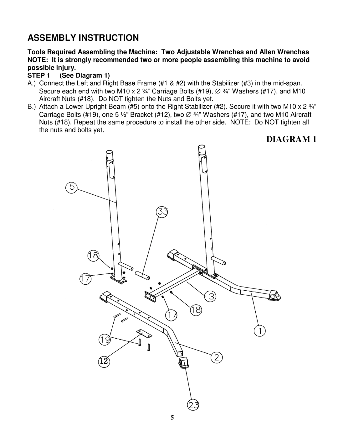
STEP 1 (See Diagram 1)
A.) Connect the Left and Right Base Frame (#1 & #2) with the Stabilizer (#3) in the
B.) Attach a Lower Upright Beam (#5) onto the Right Stabilizer (#2). Secure it with two M10 x 2 ¾” Carriage Bolts (#19), one 5 ½” Bracket (#12), two ∅ ¾” Washers (#17), and two M10 Aircraft Nuts (#18). Repeat the same procedure to install the other side. NOTE: Do NOT tighten all the nuts and bolts yet.
DIAGRAM 1
5